03-09-05 36
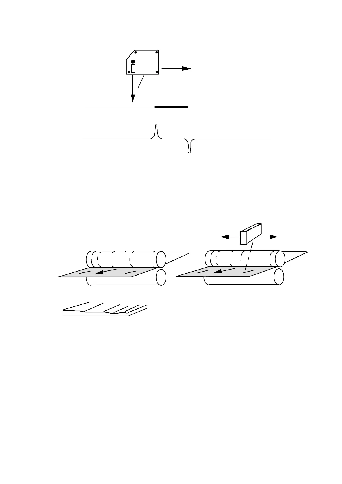
Scan
Position
output
Black strip/spot
SLS5000SLS5000
Figure 29: Example of output from the SLS sensor
Surfaces with a regular pattern from machining (e.g. rolling marks or from
grinding) will cause a uniform scattered reflection. This will result as a static error
that varies depending on where on the machining marks the center of gravity of
the light spot is located. Scanning across the marks and averaging the measured
data can eliminate this error.
FIGURE 1A
FIGURE 1B
FIGURE 2
Figure 30:
Fig. 1 A The regular surface is often produced in a rolling mill and looks like
a rib mark structure along the strip.
Fig. 1 B In other words regular thickness variations across the strip.
Fig. 2
The SLS sensor should be mounted parallel to the ”ribs” and with a
scanning direction across the direction of travel.
Advise
1 If possible orient the optical triangle parallel to surface irregularities.
2 If possible try to calibrate by letting the laser spot scan over a distance
(e.g. 10 mm) of the surface, to eliminate static texture error.
3 Calculate an average over distance when measuring.