03-09-05 52
if power is on AND the jumper or a remote switch is closed.
C Two SLS sensors connectors, SLS1 and SLS2. Socket connectors for easy
connection of one or two SLS sensors with DSUBmin connectors.
. . . . .
. . . . .
. . . . .
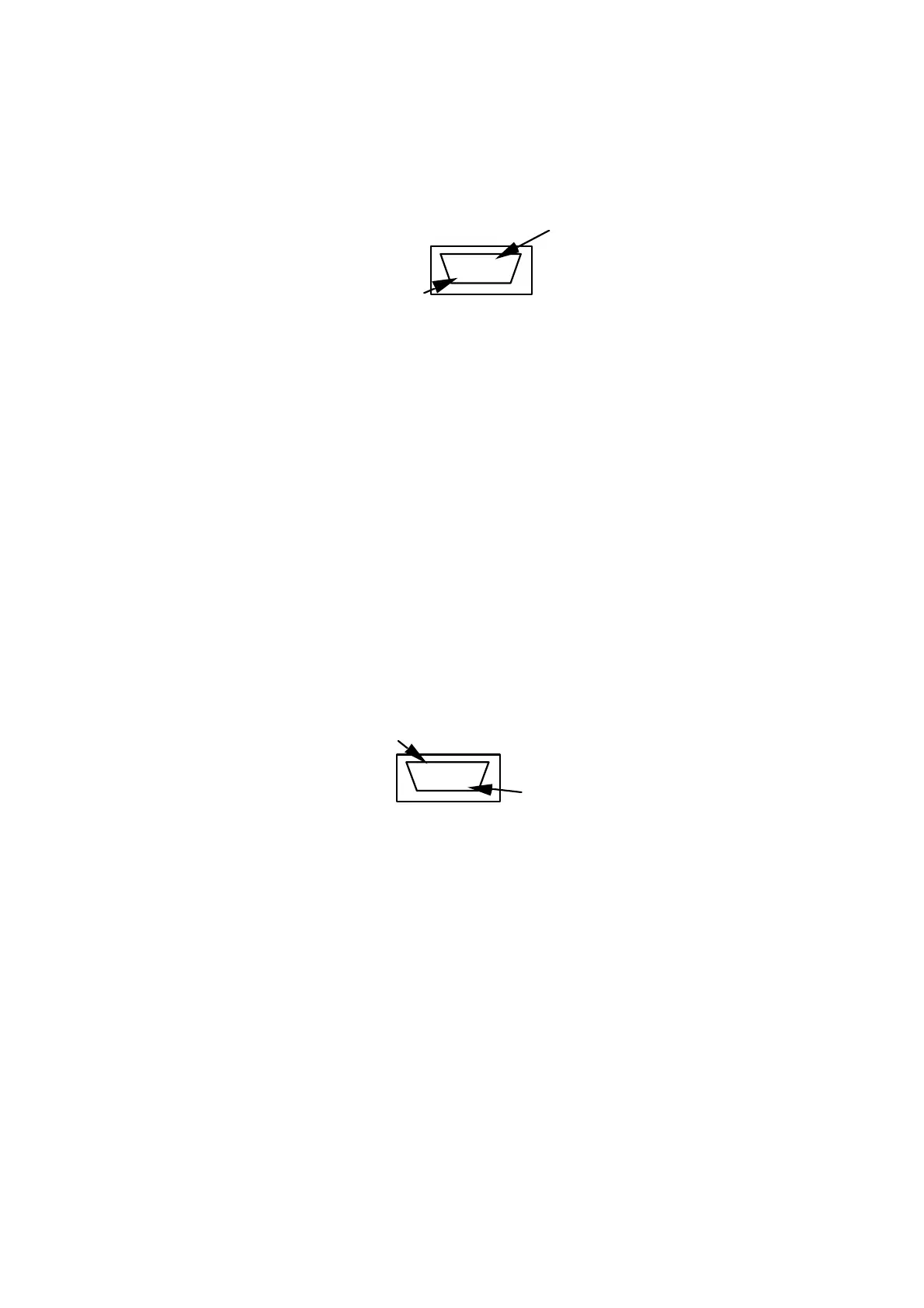
1
15
Front view, DSUB-15 pin, socket connector
SLS Powerbox 24
connectors SLS1 and SLS2
1 Receive data, RS232-C
9 Transmit data, RS232-C
3 CLOCK, SELCOM interface or RS422 Rx+
4 CLOCK-inv, SELCOM interface or RS422 Rx-
5 DATA, SELCOM interface or RS422 Tx+
6 DATA-inv, SELCOM interface or RS422 Tx-
8 Invalid out-, (when analog interface is used)
12 Invalid out + , (when analog interface is used)
13 Analog out
11 Ground
14 Laser ON, (+24 VDC)
15 Power, (+24 VDC)
Figure 34: SLS1 and SLS2 connector pin configuration
D Two output connectors, H1 and H2.Pin connectors with capacity to output all
signals available from the SLS sensor.
. . . . .
. . . . .
. . . . .
1
15
Front view, DSUB-15 pin, pin connector SLS Powerbox 24
connectors H1 and H2
1 Receive data, RS232-C
9 Transmit data, RS232-C
3 CLOCK, SELCOM interface or RS422 Rx+
4 CLOCK-inv, SELCOM interface or RS422 Rx-
5 DATA, SELCOM interface or RS422 Tx+
6 DATA-inv, SELCOM interface or RS422 Tx-
8 Invalid out-, (when analog interface is used)
12 Invalid out + , (when analog interface is used)
13 Analog out
11 Ground
Figure 35: H1 and H2 connector pin configuration