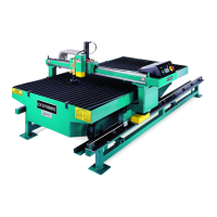
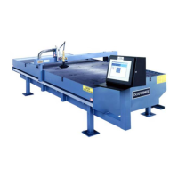
The following information outlines the factory procedures for preliminary installation of the Lockformer
Vulcan Cutting Machine. Appropriate Lockformer reference and assembly drawings accompany
this manual as section 4.
1. SAFETY - Voltages used on this machine are potentially hazardous. Therefore, all equipment
must be installed and maintained in accordance with local requirements and National Electrical
Codes. Also see the SAFETY FIRST section of this manual.
2. UNCRATING - The machine’s crating should ensure that all components arrive in good order,
but as the assemblies are uncrated, check all contents with the packing list for possible damage from
shipping. If anything shows up missing, or damaged, notify the carrier in writing at once. It is the
responsibility of the receiver to file any claims for damage against the carrier. As each assembly or
detail is unpacked, it should be placed in a suitable dry area and have its preservative removed by
use of a nontoxic fluid. Avoid the use of trichlorethylene or perchloroethylene, and ensure that the
cleaning area is well ventilated.
3. LOCATION OF MACHINE - The Vulcan needs a floor space where vibration is at an
absolute minimum. Precision operation is necessary for accurate cutting, thus avoid areas where
the transmission of any heavy vibration, (from trucks, factory equipment, etc.) may occur nearby.
Choose a site for the Vulcan near gas and electrical outlets, and if possible, near any related
production lines, for manufacturing efficiency. Material handling is also important, so be sure to
provide space for stockpiling material and moving it by hoist, truck, or other means. Adequate lighting
and ventilation must be available for safety reasons, as noted in the safety material.
Machine Grounding - Connect and maintain good electrical grounds to supply ground wire and
machine rail. Do not ground to electrical conduit or pipes carrying gases or
flammable liquids. Use
only recommended sizes of electrical cable. See page 3 for details.
4. CHECKLIST FOR RAIL SYSTEM RAILS - The Machine is factory shipped with all
Rails aligned correctly, but it is recommended that such alignments be rechecked after arrival and
initial placement of machine at its permanent operating site.
To Check the Rails, perform the following steps:
1. Use the jacking screws on the pedestals to level table over each pedestal to within 1/32".
2. Level outboard table Guide Rail to within 1/32".
3. Use the levelling screws to level Guide Rail and Outboard Rail (crossways).
4. Straighten Guide Rail to within .005".
5.
NOTE! This Step is for DUAL TABLE SETUPS Only: Check Rail joints; Rail ends must be in tight,
positive contact and flush across top and sides of Guide Rail and top of outboard Rail.
6. Check Rail Spacing on X Axis, across carriage; if not 73" +/- 1/32", loosen outboard Rail and
reposition it as required to set this dimension.
7. Recheck Steps 1 through 6.
8. Anchor the table(s) to floor securely with lag bolts.
NOTE: Such fastening can only be performed
after all alignments of machine are verified; then, customer must use any procedures desired to
secure table, ensuring that Machine and its Rails remain stationary,
which is vital.
Page 1
H. WEISS MACHINERY & SUPPLY
H. WEISS MACHINERY & SUPPLY
PHONE: (718) 605-0395 - www.hweiss.com