EasyManua.ls Logo

Logic DLC NET Series

Logic DLC NET Series
78 pages
To Next Page IconTo Next Page
To Previous Page IconTo Previous Page
Loading...
USE AND MAINTENANCE MANUAL DLC
NET
Series
Installation
LOGIC S.r.l. - M0145Db.docx
Mod. L0006A01 of 30/05/2016
Page 23 of 78
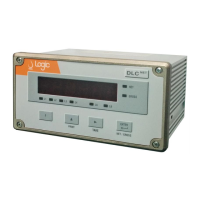
Figure 14. Load cells connection 6 wires with active barrier D1063S
3.5.4 Connection to the
junction box
The instruments of DLC
NET
series support up to 4 cells, that can be connected in
parallel. In this case it is possible to use the junction box mod. JBOX-V3 (or JBOX-
V3-EX1 in areas with potentially explosive atmospheres) for connecting up to 4
load cells and go out with a single CAB-TS6 extension cable. The connections are
shown in Table 5 and in Figure 15.
Table 5. Connection to the junction box JBOX-V3(EX1)
Table of signal and color code cable
Extension cable CAB-TS6
Terminal TB5
Signale
Description
Color Code
1
GND / Shld
cable shield
GND / Shld
2
+Exc
+ excitation
Red
3
+S
+ sense
Green
4
- Exc
- excitation
Blue
5
- S
- sense
Grey
6
+ Sig
+ signal
White
7
- Sig
- signal
Yellow
Cavi celle di carico
TB1 TB2
TB3 TB4
Signale
Description
Color Code
1
+ Exc
+ excitation
Red
2
- Exc
- excitation
Black
3
+ Sig
+ signal
Green
4
- Sig
- signal
White
5
GND / Shld
cable shield
GND / Shld

Table of Contents