USE AND MAINTENANCE MANUAL – DLC
NET
Series
LOGIC S.r.l. - M0145Db.docx
Mod. L0006A01 of 30/05/2016
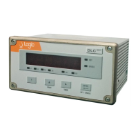
Figure 21. External buttons connection from active source
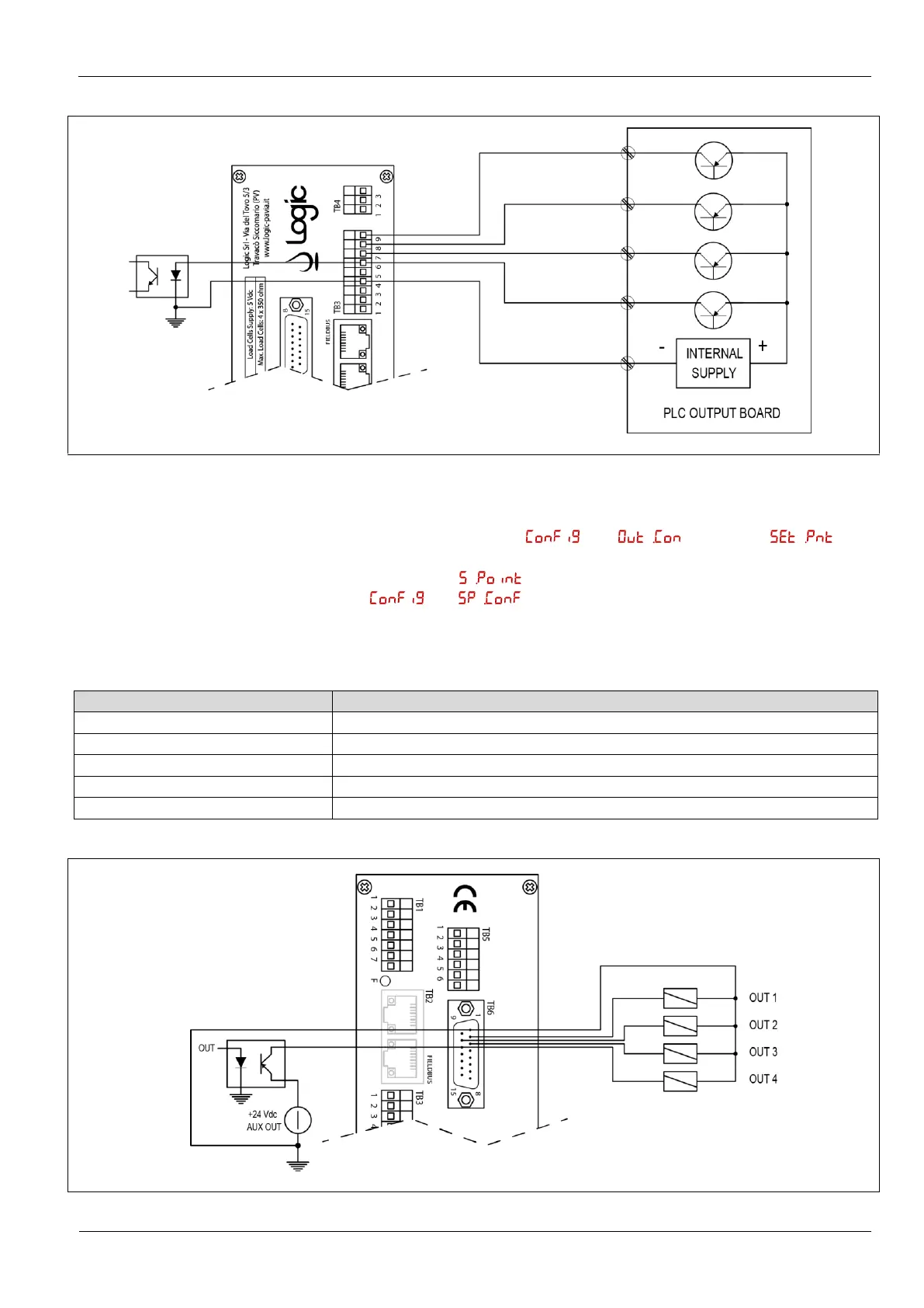
3.8.3 Connection to
setpoint output
In setpoint mode (in the menu is selected ), the
instrument activates four alarm outputs that are activated depending on the
setpoint chosen in the menu and at the intervention mode chosen (high
or low) in .
Connections are described in Table 14 and Figure 22.
It is necessary the expansion board -EB.
Table 14. Connection to setpoint output
Out 1 (+24 Vdc transistor open-collector PNP), setpoint 1
Out 2 (+24 Vdc transistor open-collector PNP), setpoint 2
Out 3 (+24 Vdc transistor open-collector PNP), setpoint 3
Out 4 (+24 Vdc transistor open-collector PNP), setpoint 4
Figure 22. Connection to setpoint output
 Loading...