USE AND MAINTENANCE MANUAL – DLC
NET
Series
LOGIC S.r.l. - M0145Db.docx
Mod. L0006A01 of 30/05/2016
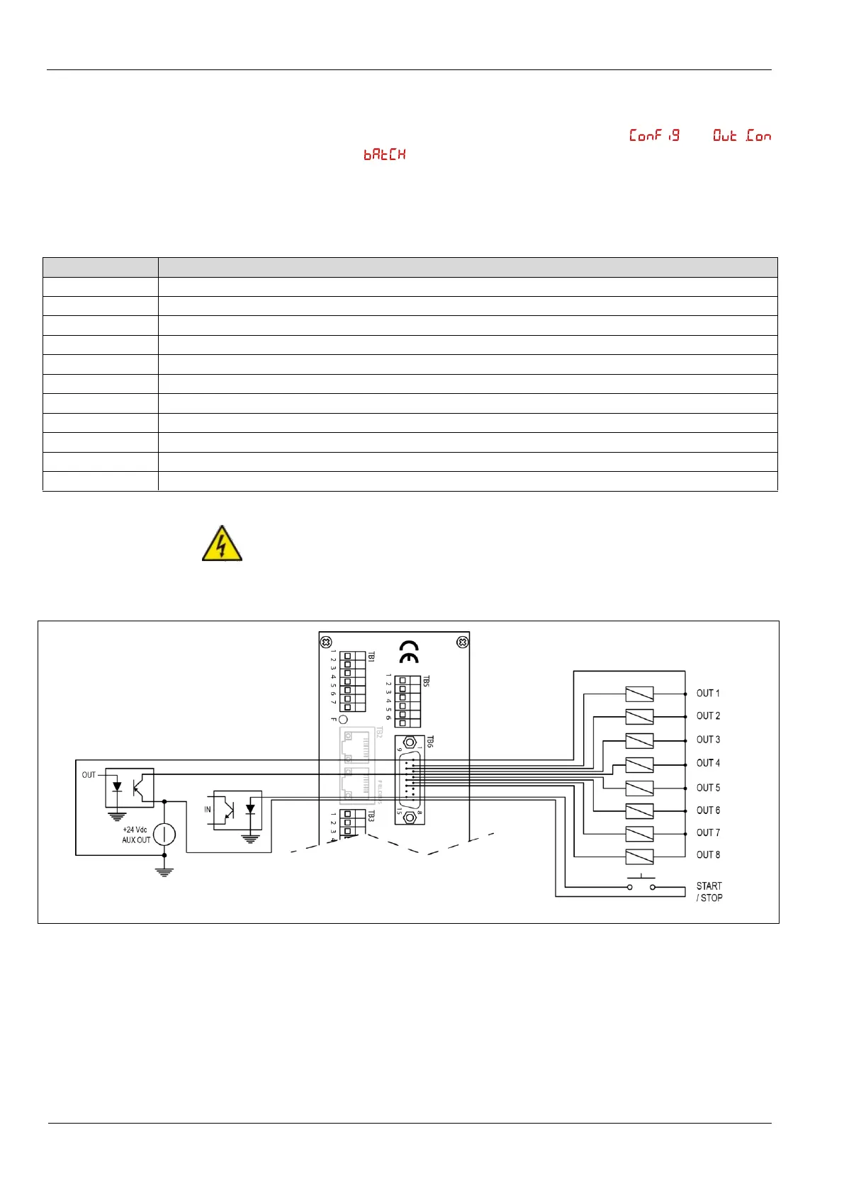
3.8.4 I/O connections in
Batch mode
When the instrument is configured as a dosing device (in
menu is selected ), the instrument uses 8 outputs for the control of solenoid
valves and pumps and an additional input for the Start / Stop button.
Connections are described in Figure 23 and Table 15.
It is necessary the expansion board -EB.
Table 15. I/O connections in Batch mode
Out 1 (+24 Vdc transistor open-collector PNP), solenoid valve output (instant) ingredient 1
Out 2 (+24 Vdc transistor open-collector PNP), solenoid valve output (instant) ingredient 2
Out 3 (+24 Vdc transistor open-collector PNP), solenoid valve output (instant) ingredient 3
Out 4 (+24 Vdc transistor open-collector PNP), solenoid valve output (instant) ingredient 4
Out 5 (+24 Vdc transistor open-collector PNP), pump output (delayed) ingredient 1
Out 6 (+24 Vdc transistor open-collector PNP), pump output (delayed) ingredient 2
Out 7 (+24 Vdc transistor open-collector PNP), pump output (delayed) ingredient 3
Out 8 (+24 Vdc transistor open-collector PNP), pump output (delayed) ingredient 4
+24 Vdc out start/stop push button
In start/stop push button
For the control of solenoid valves and pumps always lean on relay 24Vdc,
max. 50mA (100mA total, a maximum of two simultaneously active outputs).
Figure 23. Input and output connections for dosing
3.8.5 Analog ouput
connection 0-20 mA
or 4-20 mA
The analog output 0-20 mA or 4-20 mA connections are highlighted in the table
and figure below.
It is necessary the expansion board -EB.
 Loading...