USE AND MAINTENANCE MANUAL – DLC
NET
Series
LOGIC S.r.l. - M0145Db.docx
Mod. L0006A01 of 30/05/2016
4.2 Fieldbus communication
4.2.1 PLC hardware setting
The shared data structure is the same for both versions of the Fieldbus. It consists
of a total of 2 input bytes from PLC and 8 output bytes to the PLC.
Then, the hardware configuration made in the PLC software will have 2 output
bytes and 8 input bytes.
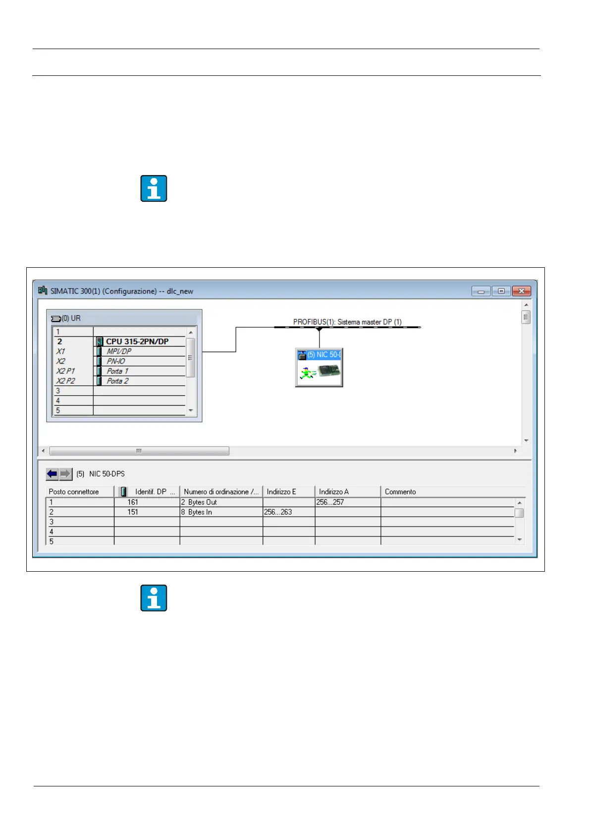
In the PLC hardware configuration always put before 2 bytes of output to 8
bytes of input. Otherwise you cannot establish communication.
Figure 31 shows an example of hardware configuration for Siemens PLC in
Simatic Step 7
®
development environment.
Figure 31. Hardware setting for Siemens PLC
For the supply of the GSD library files for Profibus-DP
®
Protocol and GSDML
for Profinet
®
contact the customer service Logic.
4.2.2 Data structure
Looking at the PLC side, the data structure provides 2 output bytes and 8 bytes of
input. Especially, you can read the data weight from the instrument in 32-bit
format, a diagnostic word and stable weight threshold currently set, also
expressed as a 16bit word. The 2 output bytes are used to set within the
instrument a new value of the stable weight threshold.
The exact meaning of each data exchanged is described in Table 22.
 Loading...