USE AND MAINTENANCE MANUAL – DLC
NET
Series
LOGIC S.r.l. - M0145Db.docx
Mod. L0006A01 of 30/05/2016
8 FIGURES
Figure 1. Equipment back serigraphy ......................................................................................................................... 11
Figure 2. Diagram of operation and power supplies ................................................................................................... 13
Figure 3. Mechanical drawing of DLC
NET
.................................................................................................................... 15
Figure 4. DLC
NET
-WM mechanical drawing ................................................................................................................ 16
Figure 5. DTR
NET
-WM mechanical drawing ................................................................................................................ 16
Figure 6. Layout of the terminal blocks, Profibus-DP
®
............................................................................................... 18
Figure 7. Layout of the terminal blocks, Profinet
®
...................................................................................................... 18
Figure 8. DLC
NET
-WM terminals (model with on-board keyboard) ............................................................................. 19
Figure 9. DTR
NET
-WM terminals (model with external keyboard) ............................................................................... 19
Figure 10. Power supply connection .......................................................................................................................... 20
Figure 11. Load cells connection 6 wires ................................................................................................................... 21
Figure 12. Load cells connection 4 wires ................................................................................................................... 21
Figure 13. Load cells connection 6 wires with Zener barrier Z-SET3-PF ................................................................... 22
Figure 14. Load cells connection 6 wires with active barrier D1063S ........................................................................ 23
Figure 15. Connection to the junction box JBOX-V3(EX1) ......................................................................................... 24
Figure 16. Connection of DLC
NET
at display DLC3-RD .............................................................................................. 25
Figure 17. Connection of DLC
NET
to display BEKA
®
BA488C .................................................................................... 26
Figure 18. Instrument connection to Profibus-DP
®
Fieldbus ...................................................................................... 28
Figure 19. Instrument connection to Profinet
®
Fieldbus ............................................................................................. 29
Figure 20. Connection to external buttons through potential-free contacts ................................................................ 30
Figure 21. External buttons connection from active source ....................................................................................... 31
Figure 22. Connection to setpoint output .................................................................................................................... 31
Figure 23. Input and output connections for dosing ................................................................................................... 32
Figure 24. Analog output connection 0-20 mA or 4-20 mA ........................................................................................ 33
Figure 25. Printer connection through RS232 ............................................................................................................ 34
Figure 26. Signal chart for the data weight reading through parallel output ............................................................... 35
Figure 27. Connection for parallel interface type PNP ............................................................................................... 36
Figure 28. Connection for parallel interface type NPN ............................................................................................... 37
Figure 29. Switch SW2-1 for setting speed ADC........................................................................................................ 39
Figure 30. Termination resistance setting RS485 serial port ..................................................................................... 39
Figure 31. Hardware setting for Siemens PLC ........................................................................................................... 40
Figure 32. Reading instrument with PLC .................................................................................................................... 42
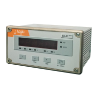
Figure 33. Operator interface of DLC
NET
instrument ................................................................................................... 43
Figure 34. Operator interface with Logic DLC3-RD .................................................................................................... 43
Figure 35. Operator interface with BEKA
®
BA488C ................................................................................................... 44
Figure 36. Application of the instrument as a batcher ................................................................................................ 61
Figure 37. Timing activation outputs for the dosing of automatic components .......................................................... 62
 Loading...