PAGE 38 OPTIONAL EQUIPMENT (CONTINUED)
REAR BLOWER INSTALLATION (CONTINUED)
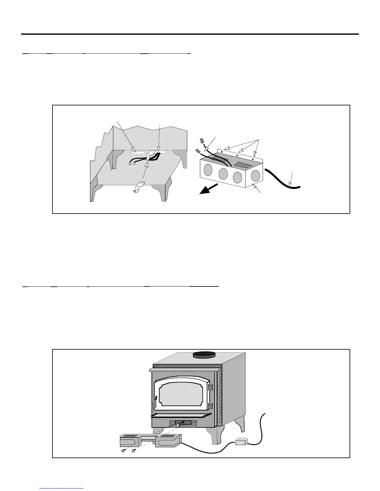
3. Slide the wire clip over the metal between the two knock-outs removed in step 1 (see the
illustration below). Run the two wires from the thermodisk assembly through the wire clip and
pull the slack wire out of the stove. The wires coming from the thermodisk assembly must not
have any slack Ð these wires may cause a short if the wires come in contact with the firebox.
Remove enough slack to eliminate the wires rubbing on the firebox, but do not tighten so as to
dislodge the thermodisk assembly.
The two yellow wires
attach to the thermodisk.
Three holes for
attaching the
blower box to the
back of the stove
Power Cord
(exits from back
of blower box)
FRONT
Blower Box
Slide the wire clip over the
edge of the strip of metal
between the two knock-outs.
Feed the two
thermodisk wires into
the eye of the wire clip.
These knock-outs
must be removed.
4. Route the two yellow wires from the blower box through the top portion of the blower assembly
(the wires must not exit out the hole in the back of the blower box). Connect these wires to the
two wires from the thermodisk assembly (orientation does not matter).
5. Place the blower box near the bottom rear of the stove and push any slack wire into the blower
box so that when the blower box is attached the excess wire will not contact the stove. Attach
the blower box to the stove with the three screws included with the blower kit (use a 3/8"
nutdriver). You may wish to pre-thread the holes in the back of the stove prior to putting the
blower box in place.
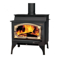
FRONT BLOWER INSTALLATION (PART NUMBER 99000128)
The front blower is designed to improve the natural convection of the appliance by pushing air through
the convection chamber of the appliance and causing the heated air to exit through the vents along the
top of the appliance. It attaches below the ashlip. Operating instructions are described in the section
"Blower Operation" on page 24. The directions below detail its installation.
1. Remove the two screws located underneath the ashlip (see the illustration below).
2. Place the blower underneath the ashlip and re-attach the screws. Before tightening the screws,
lift up on the blower so that it tucks up underneath the ashlip closely.
Control Box
Use a 3/8"
nutdriver to
attach the two
screws that hold
the front blower
to the appliance.
Plug the blower
into a 110 volt
grounded outlet.