Starting up
- 40 - 01.21909.2669.9-02
14.4 Powermaster parameters
All Powermaster torches of the i-LTG/i-LTW – serie have two
free programmable parameter spaces (PL3 and PL4).
 Select sub parameter PL3 or PL4.
9 The 7-segment display 38 shows alternating code PL3 or
PL4 and the code of the selected Powermaster parameter.
 Select the required Powermaster parameter with the turn-
ing knob 41.
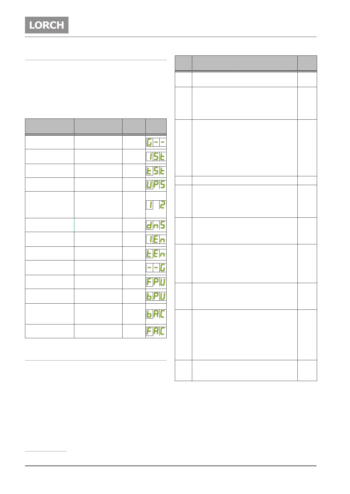
Parameter Range
Factory
setting
Code
Gas pre-ow time 0,1 - 10 sec 0,1
Start current IS
5 - 200 %
of main current
50
Start current time 0 - 20 sec. 0,1
Upslope 0 - 99 % 5
Second current I2
1 - 200 %
of main current
representation in
Amp.
50
Downslope 0 - 99 % 20
Final current IE
5 - 200 %
of main current
25
Final current time tE 0 - 20 sec. 0,2
Gas post-ow time
correction
20 - 500 % 100
Pulse frequency 0,2 - 2000 Hz 5
Pulse duty factor
1 - 99 %
Main current I1
50
AC-balance
1
10 - 90 %
positive welding
current
35
AC-frequency
1
30 - 200 Hz 60
Tab. 4: Powermaster parameters
1)
14.5 User-specic menu
 Switch o the equipment at the main switch 9.
 Press the selection button on the left 30 and keep it de-
pressed.
 Switch on the equipment at the main switch 9
9 The user-specic menu is activated. The menu item and its
set value are shown alternating in the 7-segment display
38
 Press the selection button 30 or 47 to switch among the
menu items.
 Turn the control dial 41 to change the set value.
1)
Only for AC/DC
Menu
no.
Menu item
Setting
values
C00 Display and adjustment of the torch-ID. See „Ad-
justment of the torch-ID“ on page 41.
9...45
C01 Welding current limit for up/down torch. When
the welding current limit is switched to “On”, the
welding current on the up/down torch cannot
be set higher than pre-selected on the control
terminal.
On-O
C02 Deactivation of the error message E05-00 (water
pump) and of the water cooling unit by Lorch-
Net.
If the deactivation is switched “on”, the error mes-
sage E05-00 (water pump) is no longer displayed.
Also the water cooling unit is not switched on by
LorchNet.
Practical, e.g. for the use of an automatic torch
without plug or a cooling unit without LorchNet.
On-O
C03 Activation of the orbital welding mode. On-O
C04 ON: at short circuit the welding current don’t
increase the adjusted welding current shown in
the display (set value).
O: at short circuit the welding current is in-
creased on minimum 60 A.
On-O
C05 ON: by quick pressing of torch button 1 (start /
stop) the 2nd torch button is simulated.
(Second current on / o). Useful e.g. for torches
with one button only.
On-O
C06 ON: the current decrease (downslope) will be - as
adjusted – conducted, also if the torch button is
released (4th tact).
O: at earlier release of the torch button (4th
tact) the current decrease (downslope) is inter-
rupted.
On-O
C07 On: PE conductor monitoring activated
O: PE conductor monitoring deactivated
the PE conductor monitoring is an optional avail-
able feature
On-O
C08 O: Using a foot remote control, the minimum
current (independent from the adjusted welding
current) in the TIG mode / AC at
electrode-Ø 1,0...2,0 mm = 10 Amps
electrode -Ø 2,4 mm = 15 Amps
electrode -Ø 3,2 mm = 20 Amps
On: the increased minimum current in the TIG-
mode / AC is deactivated
On-O
C10 Welding current limit
0 = O
I1
Min
...I1
Max
= On
0,
I1
Min
...
I1
Max
Tab. 5: User-specic menu
 Switch the equipment o at the main switch 9 to transfer
the settings from the user-specic menu.
 Loading...