Basic Setup (LH150 Series)
6
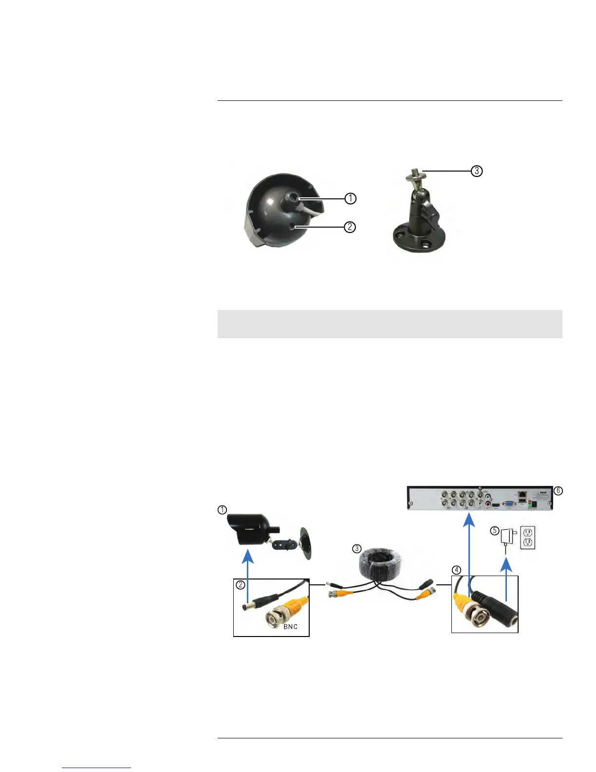
There are two connection points for certain cameras. Secure the stand to the top thread
for wall mounts or ceiling mounts. Secure the stand to the bottom thread for table mounts
or wall mounts.
1. Top Thread (Ceiling Mount, Wall Mount).
2. Bottom Thread (Table Mount).
3. Secure to camera thread.
Note
Camera model may not be exactly as shown.
6.11.2 Connecting BNC Cameras to your DVR
1. Connect the male power connector on the BNC extension cable to the female power
connector on the camera.
• Connect the BNC connector to the camera.
2. Connect the female power connector on the BNC extension cable to the power
adapter.
3. Connect the BNC connector to one of the Video Input ports on the rear panel of the
DVR.
4. Plug the camera power adapter to a power outlet.
Camera Installation Diagram
1. Camera.
2. End of extension cable with male power connector.
3. Extension cable.
4. End of extension cable with female power connector.
5. Camera power adapter.
6. DVR.
#LX400012; r. 2.0/12066/12066; en-US
15
 Loading...