MOWER ASSEMBLY
The mower is pre-assembled at the factory; however, parts in the bag and box must be assembled.
Use the present manual and lay out all parts for assembly. Separate bolts and nuts into various sizes.
After assembly, torque all the bolts according to the "Torque Specification Table" enclosed at the end
of the manual.
MOWER INSTALLATION
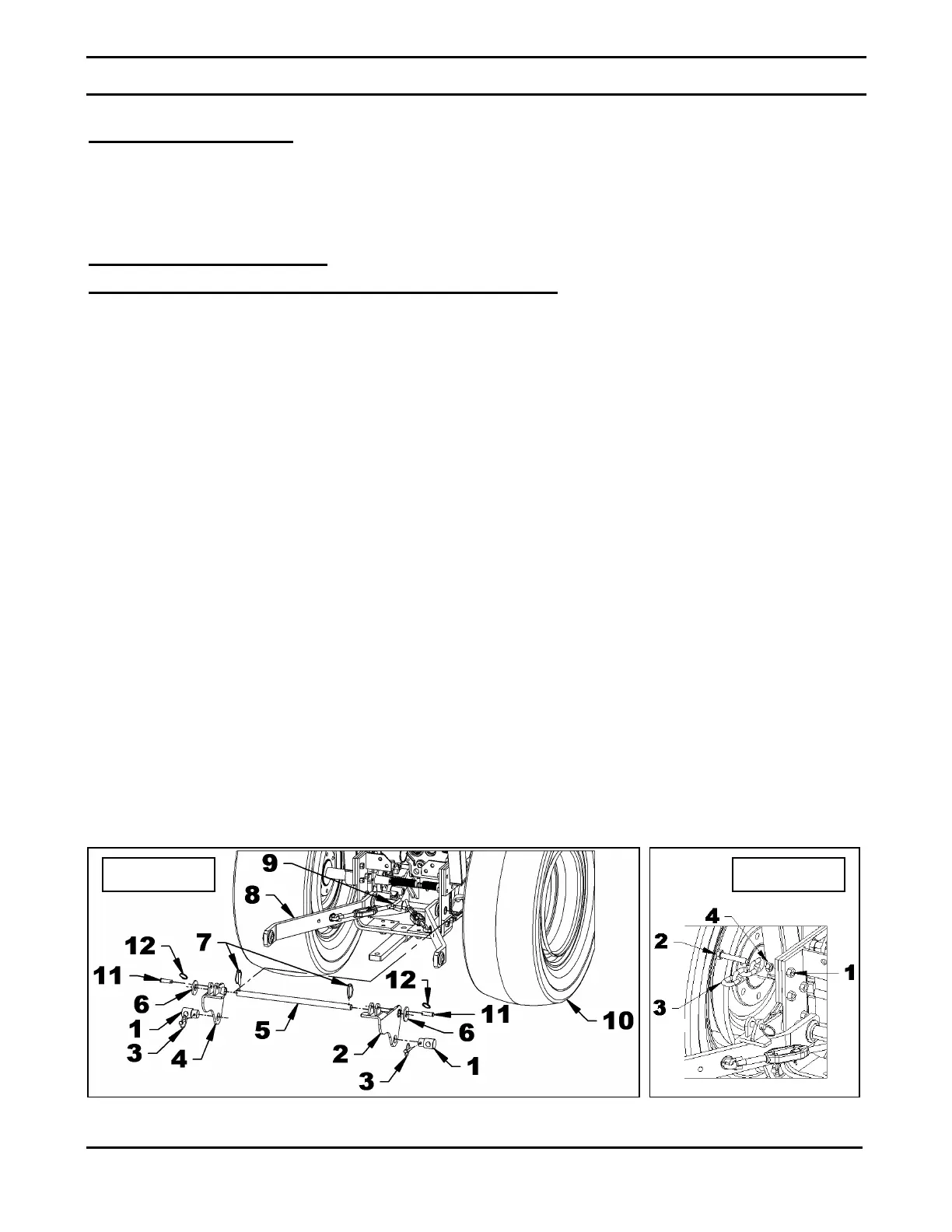
Installation of Tractor 3 Point Pins & Lifting Pivots (fig.1-2)
1. Park the tractor on a level surface and
flat. Apply the parking brake.
2. Lift the rear of the tractor with a jack
and take care to block the tractor
wheels to prevent movement during
the installation of components.
Remove one of the rear tractor wheels
(item 10).
3. Remove the pivot pin on the opposite
side of the tractor wheel removed.
Remove the shaft pin of the 3 point
lower arm. It will not be reused for the
installation of the mower.
4. Figure 1: Attach the pivot spacer
(item 1) to the 3 point lifingt pivot (item
2) with a 5/16" linchpin (item 3). The
pivot spacer (item 1) must point in the
opposite direction of the lifting pivot
fold (item 3). Repeat for the other pivot
(item 4).
5. Figure 1: Insert the pivot pin (item 5) in the lifting
pivot (item 2), the tractor frame (item 7), the 3 point
lower arm, the anti-sway bars (item 9) then in the
second 3 point lower arm (item 8), the tractor frame
and finally in the other lifting pivot (item 4).
6. Figure 1: Install a 7/8" flat washer (item 6) on each
end of the pivot pin (item 5) and secure with a 5/16"
linchpin (item 7).
7. Figure 1: insert a 1/2" x 1 3/4" pin (item 11) in each
3 point lift pivot (items 2 & 4) and secure with a
circle cotter (item 12).
8. Figure 2: Insert the last link of the chain (item 3) on
the M12 x 1.75 x 70mm hex bolt (item 2) and
secure with a M12 hex nut (item 4).
9. Figure 2: Replace the existing bolt (item 1) by the
hex bolt M12 x 1.75 x 70mm (item 2) assembled
with the chain. When the bolt exceeds by 1/8" from
the tractor's welded nut, tighten the M12 hex nut
(item 4) against the tractor frame.
10. Perform the same operation on the other side of the
tractor.
 Loading...