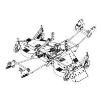
Installation of the Lifting Arms and
Connecting the Driveline to the Tractor
(figure15)
1. Figure 15: Lower the tractor 3 point hitch
completely.
2. Figure 15: Pull out the latch (item 1) until
it's completely out of the hole and rotate it
slightly until the end rests against the plate
(item 3).
3. Figure 15: Insert the lifting arm (item 2)
between the two plates (item 3), rotate the
latch (item 1) until it's inserted in the plates
(item 3) and the holes (item 2).
4. Repeat the same procedure for the other
lifting arm.
5. Figure 15: Connect the driveline (item 4) to
the tractor PTO.
CAUTION:
To avoid serious personal injuries:
Make sure that the driveline quick coupler
is securely locked in place. A "click" must
be heard. If it is not securely fastened, it
will come off the spindle shaft and spin
out of control.
WARNING:
To avoid serious personal injuries: This
shaft turns at very high RPM. If the collar
is not locked to the shaft at tractor end, or
if the yoke at the mower end is not
secured properly, the driveline can fly
loose with great force capable of causing
serious injury or death.
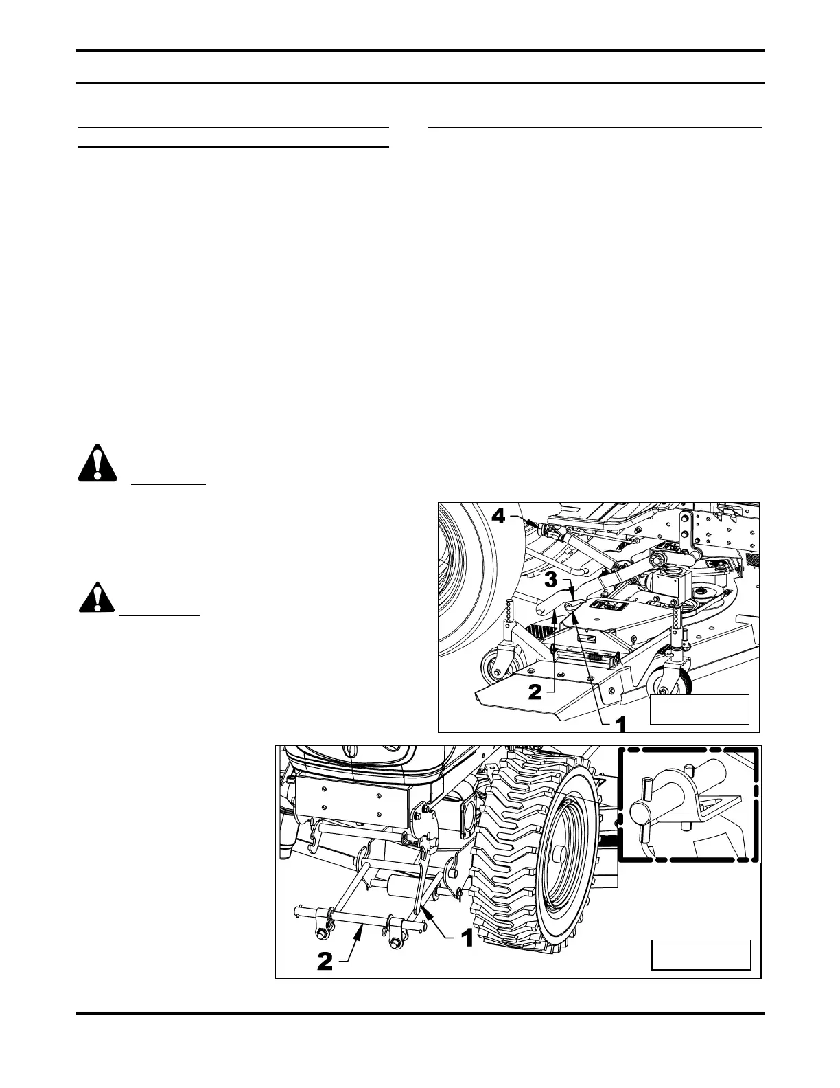
Installation of the Front Anchor Rod
(figure 16)
1. Figure 16: Remove the “T” pin from the
anchor lever rod (item 1) and lower the
anchor lever (item 1). Raise the anchor rod
(item 2) and hook it to the anchor lever (item
1). Raise it completely to lock it.
2. Figure 16: Unlock the “T” pin and let it lock
the anchor lever (item 1).
 Loading...