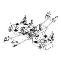
Installation of the Deflectors (figures 7-7A)
1. Figure 7: Install the rubber deflector
(item 1) between the deflector support
(item 2) and the deflector
reinforcement (item 3) and secure with
five 3/8" x 1 1/4" bolts (items 4 & A),
installing the "A" bolts first, ten 3/8" flat
washers and five 3/8" nylon insert
locknuts (items 5-6) as shown on
figure.
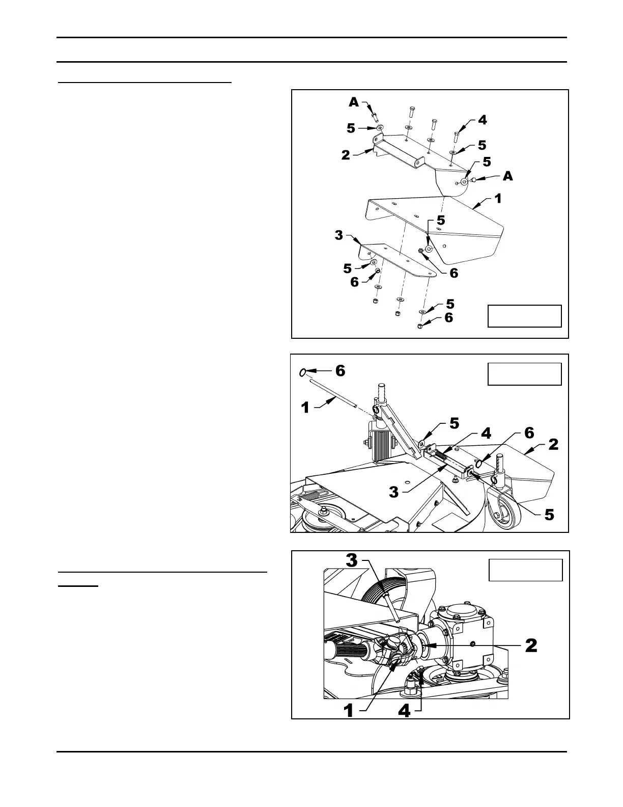
2. Figure 7A: Install the deflector
assembly (item 2) inside the support
(item 3) welded to the mower frame.
3. Figure 7A: Insert the 7/16" x 10 1/4"
deflector pivot pin (item 1) through the
support welded on the frame (item 3),
the deflector assembly (item 2) and a
torsion spring (item 4) placing the
longest spring rod on the deflector
assembly and the shortest one in the
notch of the support (item 3).
4. Figure 7A: Install a 1/2" flat washer
(9/16" hole) (item 5) at each end of the
pin (item 1) and secure with two circle
cotters (item 6).
Connecting the Driveline to the
Mower (figure 8)
Attach the driveline (item 1) to the
gearbox shaft (item 2) and secure with a
5/16" x 2 1/2" bolt (item 3) and a 5/16"
nylon insert locknut (item 4).
 Loading...