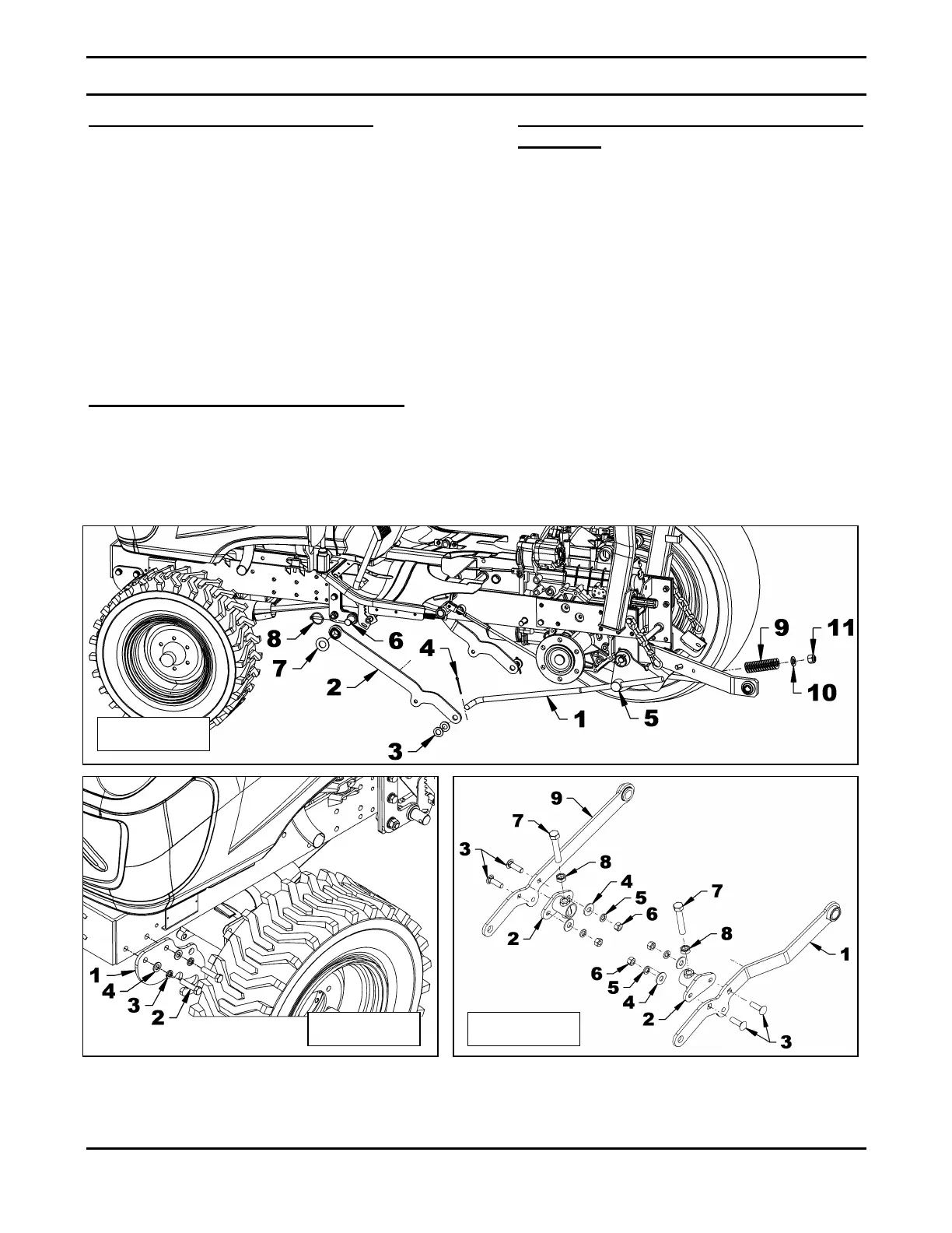
Installation of the Lifting Arms (figure 4)
1. Figure 4: Insert a lifting lever (item 1), in each
lifting arm and secure with two 3/4" flat washers
(item 3) and a 3/16" x 2" cotter pin (item 5). The
curved lifting arm (figure 5A, item 1) is installed
on the tractor right side.
2. Figure 4: Insert the lifting lever (item 1) in the
pivot spacer (item 5) and attach the lifting arm
(item 2) to the tractor bracket (item 6) with a 1"
flat washer (item 7) and a 5/16" linchpin (item 8).
3. Figure 4: Install a compression spring (item 9), a
3/4" flat washer (13/16" hole) (item 10) and a
3/4"NF nylon insert locknut (item 11) on each
lifting lever (item 1). Tighten slightly.
Installation of the Front Supports (figure 5)
1. Figure 5: Install a front support (item 1) on each
side of tractor frame and secure with two M12 x
1.75 x 50mm bolts (item 2), two 12mm
lockwashers (item 3) and two 12mm flat
washers. Tighten slightly.
Installation of the Side Bumper
Brackets (figure 5A)
1. Figure 5A: Install a side bumper bracket
(item 2) each lifting arm (item 1) with two
1/2"NC x 1 3/4" carriage bolts (item 3), two
1/2" (9/16" hole) flat washer (item 4), two
1/2” lockwashers (item 5) and two 1/2"NC
nuts (item 6).
2. Figure 5A: Screw the ø5/8”NC jam nut
(item 8) completely on the 5/8” x 3 1/2"
bolt (item 7) then screw it half way into the
side bumper bracket (item 2).
3. Figure 5A: Once the mower is installed on
the tractor, raise it completely and adjust
both 5/8” x 3 1/2" bolts (item 7) until it
touches the tractor frame, then tighten the
5/8”NC jam nut (item 8) to lock the bolt in
place. This device will prevent the mower
from raising too high and damage the
mower and the tractor.
 Loading...