Locked Position (figures.17-17A)
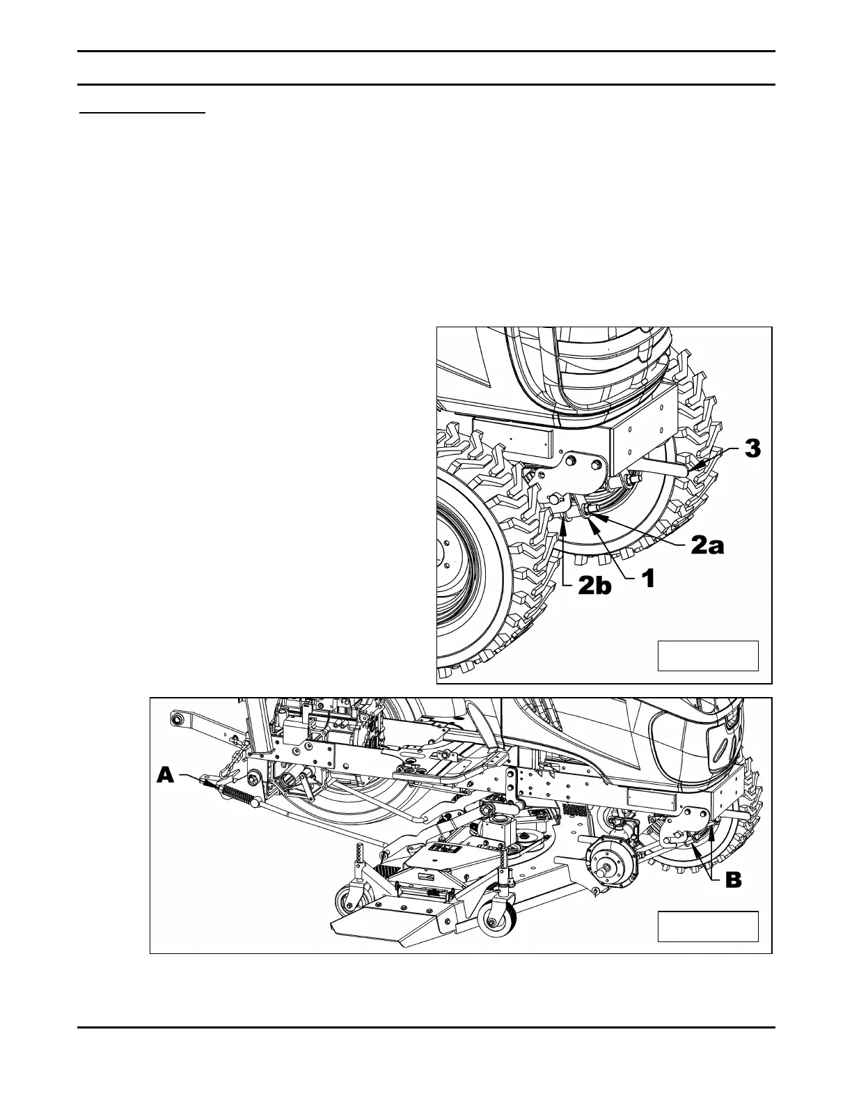
1. Figure 17A: Tighten the 3/4" nylon insert
locknut (item A) until it rests against the
compression spring. Then continue
tightening until spring compresses 1/4" (the
spring's original dimension is 5"). Measure
the threaded section that exceeds from the
nylon insert locknut and apply the same
measurement to the other nylon insert
locknut.
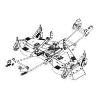
2. Figure 17: To adjust the anchor bushing
(item 1) tighten the 5/8"NC jam nut (item 2a)
then secure with the second 5/8"NC jam nut
(item 2b).
3. Repeat this procedure until the correct
adjustment is obtained.
Tightening too much will block the
anchor lever (item 3) and make it
difficult to remove and reinstall the
mower..
4. Figure 17: Pull out the anchor lever lock
pin to check that it can be easily
disengaged. If you find it difficult to
disengage, untighten the anchor bushings.
5. Tighten the anti-sway bar on each side,
making sure there is no interference with
the tires.
 Loading...