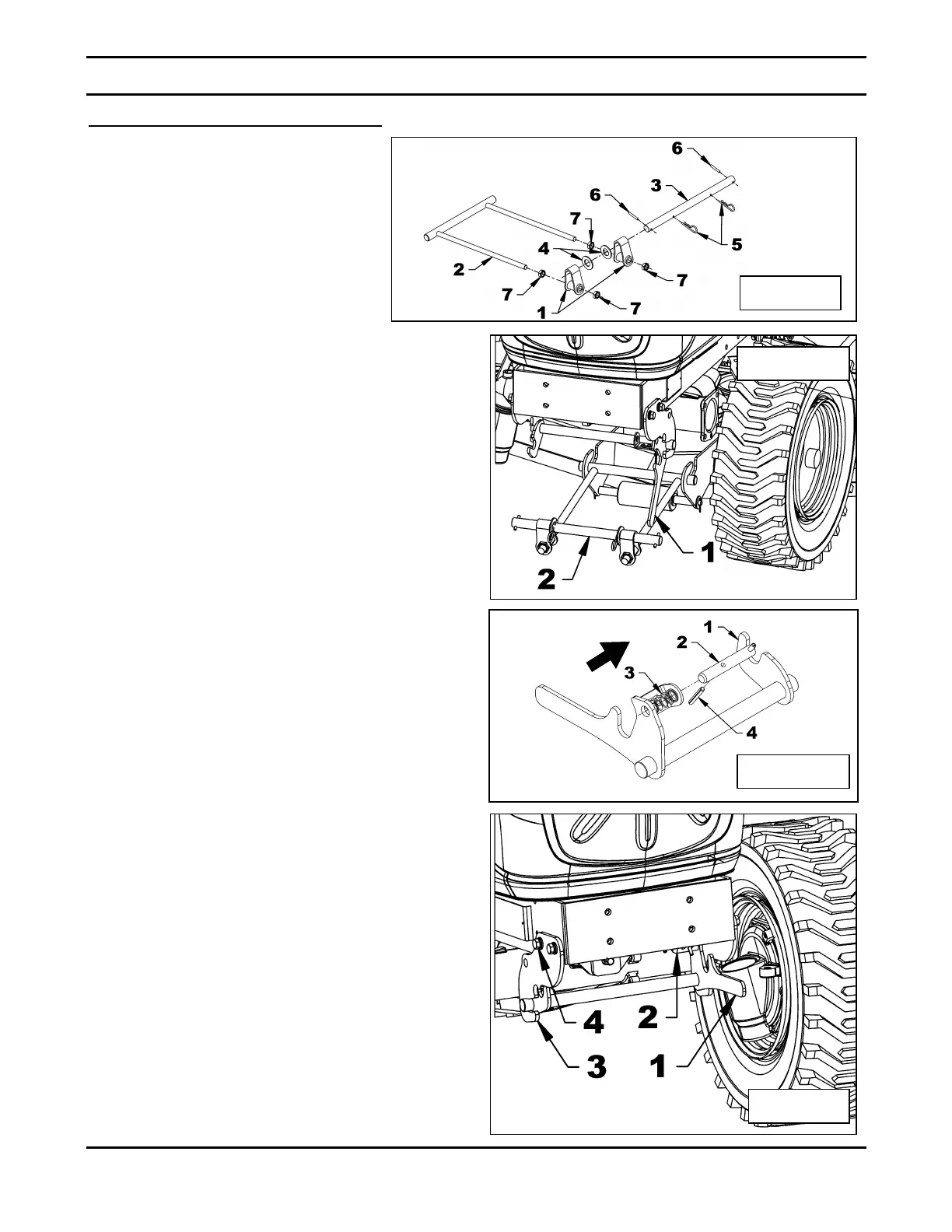
Installation of the Front Anchor (figures 9-12)
1. Figure 9: Install two 5/8"NC jam
nuts (items 7), two anchor
bushings (item 1) to the front
anchor (item 2) and two more
5/8"NC jam nuts (items 7).
2. Figure 9: Insert the 16 3/4" long
anchor rod (item 3) in the anchor
bushings (item 1) and place two 1"
washers (item 4) between the two
anchor bushings.
3. Figure 9: Press the flat washers (item 4)
against each anchor bushing (item 1) and
insert two 4mm x 80mm hairpins (item 5) in
the anchor rod (item 3).
4. Figure 9: Install a 1/4" x 1 3/4" spring pin
(item 6) on each end of the anchor rod
(item 3).
5. Figure 10: Insert the front anchor
assembly (item 2) in the mower front
anchors.
6. Figure 11: Place the 0.796"OD x 1 5/8"
compression spring (item 3) as shown on
figure, and insert the "T" pin (item 2) in the
anchor lever (item 1).
7. Figure 11: Compress the spring (item 3) in
the direction of the arrow and insert the
1/4" x 1 3/4" spring pin (item 4) in the "T"
pin (item 2) and the anchor lever (item 1)
leaving the spring pin exceed 1/4" (item 4)
from the "T" pin.
8. Figure 12: Insert the anchor lever
assembly (item 1) between the two front
supports (item 3). Raise the anchor lever
(item 1) and lock it in the front supports
(item 3) using the "T" pin (item 2).
9. Figure 12: Place the two front supports
parallel to the tractor frame and tighten the
four M12 x 1.75 x 50mm bolts (item 4),
lockwashers and flat washers. Tighten
according to the Torque Specification
Table at the end of the manual.
 Loading...