31
Control circuit Terminal Labels and Descriptions
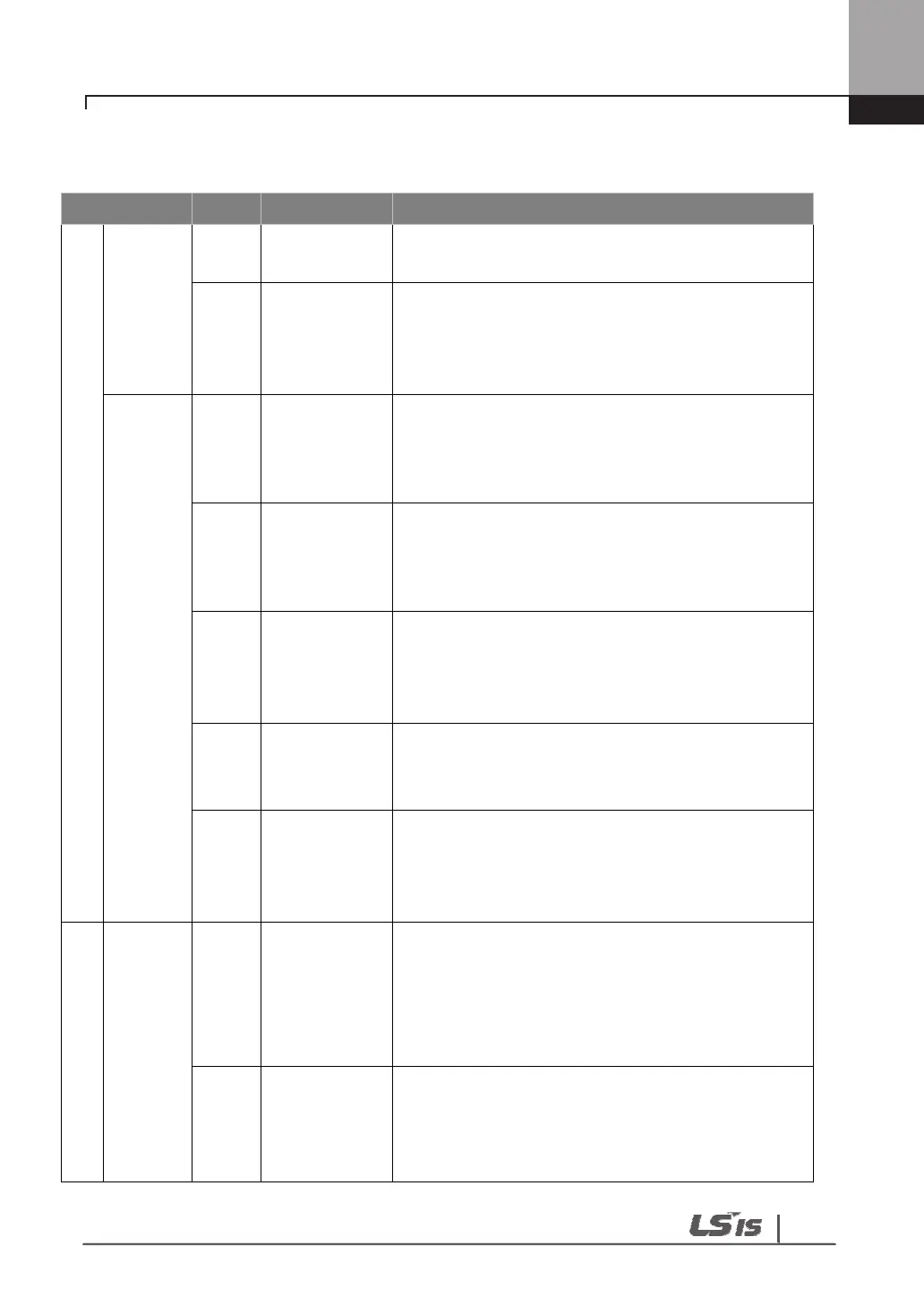
Type Label
Name Description
Input signal
Contact
point
start
function
selectio
n
P1~P
8
Multi-function
input1~8
Available by defining as multi-function input
CM
Sequence
common
terminal
Common terminal of the contact point input
terminal
(note: In case of Basic I/O, common terminal is
different from the 5G common terminal)
Analog
Frequen
cy
VR(+)
Frequency
setting
power(+)
terminal
Power supply for analog frequency setting
Maximum output is +12V, 100mA.
VR(-)
Frequency
setting
power(-)
terminal
Power supply for analog frequency setting
Maximum output is -12V, 100mA.
V1
Frequency
setting
(voltage)
Becomes set frequency with input of DC -
10~10V.
Unipolar 0~+10[V]),Biopolar(-10[V] ~10[V]) input
resistance 20kΩ
I1
Frequency
setting
(current)
Becomes set frequency with input of DC
0~20mA
input resistance 249Ω
5G
Frequency
setting
common
terminal
Common terminal of analog frequency setting
signal and analog voltage and current terminals
(note: In case Basic I/O, common terminal are
different from the CM common terminal)
Output Signal
Analog
A01
Multi-function
analog
voltage
output
terminal
Select the one among Output frequency, Output
current, and DC voltage.
Ouput voltage: 0~10V
Maximum output voltage: 10V
Maximum output current: 10mA
A02
Multi-function
analog
current output
terminal
Select the one among Output frequency, Output
current, Output voltage and DC voltage.
Output current: 4~20mA (0~20mA)
Maximum output current: 20mA

 Loading...


