p/n 18603-001, Rev. C LTV
®
1200/1150 Ventilator Service Manual Page 8-89
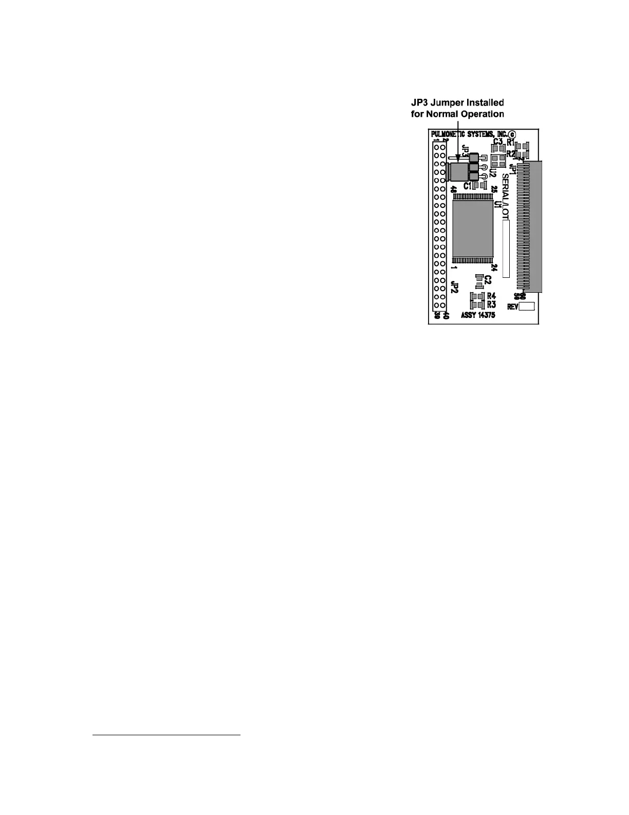
Installing the new memory board:
1) Verify jumper is installed in the Normal Operation
position of the JP3 connector (as shown), prior to
installing the memory board.
2) Install the new memory board by lining the edges up in
the supporting rails and sliding it into position. Be sure the
connector on the memory board is oriented correctly to
line up with the mating connector on the main PCBA.
Press the board in place until the connectors are firmly
seated.
3) Install an O
2
Sampling Tube
51
. See Back Panel, Reinstallation in Chapter 8 –
Component Removal and Replacement for detailed instructions.
4) Reconnect the internal battery and replace the back panel (see instructions on page 8-
29).
5) To verify the new software version, power up the vent and enter the Extended Features
menu. Select VENT OP and rotate the knob until the VER string is displayed. Verify that
the version string displayed matches the version of the newly installed software on the
memory board.
6) After upgrading the LTV
®
software version, check each of the LTV
®
configuration settings
(see Configuration, page 6-33).
7) Upgrading LTV
®
software will require recalibration of the LTV
®
ventilator. (see
Calibration, page 6-6).
51
O
2
Sampling Tube, P/N 10544, ~10.0” long, 0.125” O.D. X 0.079 I.D. clear polycarbonate tubing.