p/n 18603-001, Rev. C LTV
®
1200/1150 Ventilator Service Manual Page 6-1
Chapter 6 -
M
AINTENANCE
&
C
ALIBRATION
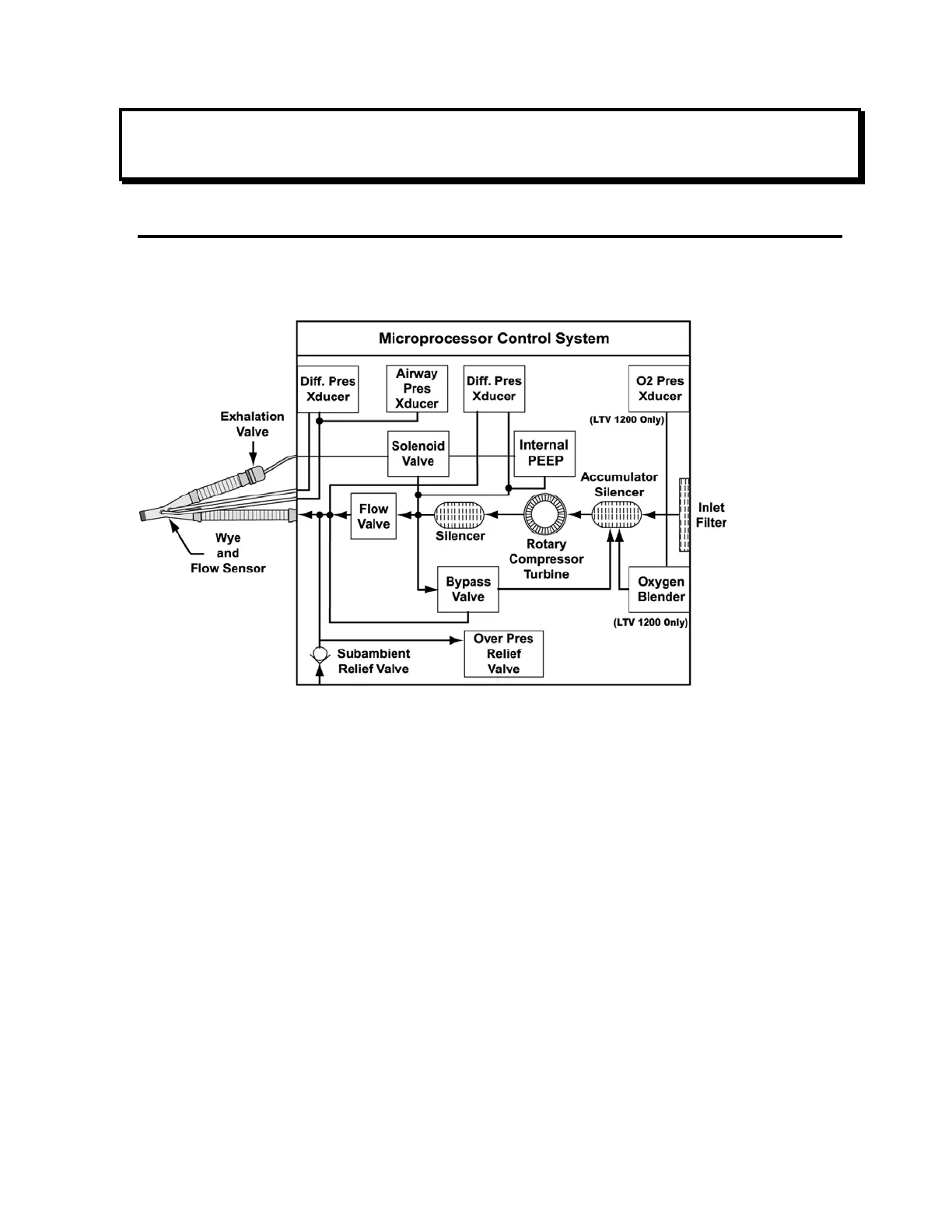
Operating Theory
The LTV
®
1200/1150 ventilator utilizes an electromechanical pneumatic system under the
control of a microprocessor to deliver patient ventilation. The following diagram and
descriptions illustrate the major components of the ventilator and their respective functions.
Room air enters the ventilator through a flexible foam Inlet filter. After exiting the filter, the air
enters an Accumulator/Silencer where it mixes with oxygen delivered from the Oxygen
Blender (LTV
®
1200 only). In addition, this chamber provides acoustic silencing to reduce the
Rotary Compressor input noise. Mixed gas then enters the Rotary Compressor Turbine,
where energy is added to the gas stream as required to meet the pressure and flow delivery
requirements of the current ventilation settings.
Gas exiting the Rotary Compressor Turbine output port enters another Silencer. This chamber
dampens acoustic noise from the Rotary Compressor Turbine. Upon exiting the silencing
chamber, the gas flow splits in two paths. Gas flow for ventilation diverts to the Flow Valve,
while excess flow is recirculated through the Bypass Valve to the inlet Accumulator/Silencer.
The Bypass Valve maintains Flow Valve inlet pressure high enough above Flow Valve outlet
pressure to ensure a positive differential pressure across the valve, yet low enough to ensure
that excess energy is not wasted when operating from batteries.
Ventilation flow enters the Flow Valve, which controls all inspiratory gas flow to the patient. The
valve is driven by a rotary actuator, and translates circular motion to a poppet position, which in
turn meters flow to the patient. The valve is characterized such that gas flow is a known function
of differential pressure across the valve and actuator position. A Differential Pressure
transducer is provided to measure the differential flow valve pressure.