p/n 18603-001, Rev. C LTV
®
1200/1150 Ventilator Service Manual Page 8-115
11) Carefully remove and discard the rotary switch assembly washer and O-ring from the
back of the ventilator through the openings in the power and main boards.
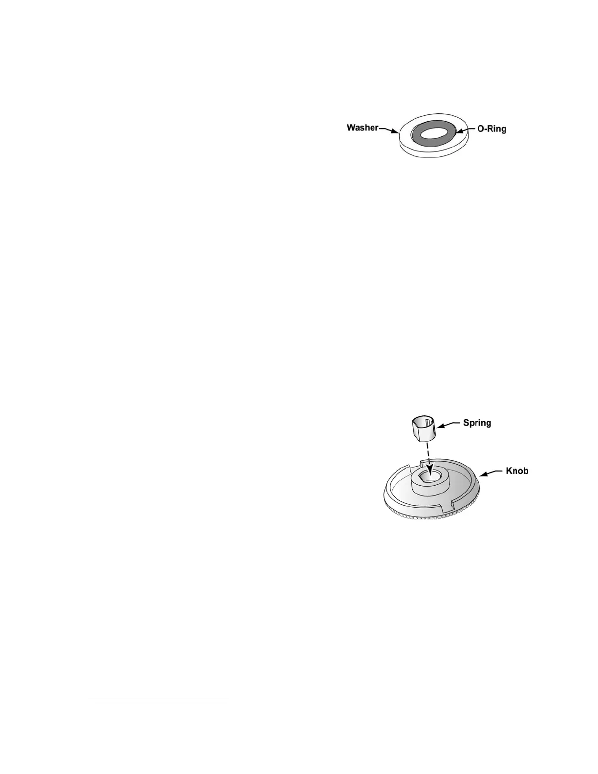
12) Place the O-Ring (P/N 11645) inside the Washer
(P/N 11644), insert them through the openings
in the power and main boards and center both
over the Rotary Knob shaft cutout in the upper
weldment.
13) Insert the new rotary switch assembly (P/N 11190) through the openings in the power
and main boards so the shaft extends through the O-ring, washer and cutout in the
upper weldment. The switch assembly should be oriented so the wire leads are towards
the same side of the ventilator as the oxygen blender.
14) Hold the switch in-place and thread the hex nut onto the rotary switch shaft. Use a
13mm nut driver and torque-tighten the nut to 40 in-oz (0.28 Nm).
15) Connect the switch assembly connector to the power board. The connector is keyed to
fit in only one direction and will snap into place when properly connected.
16) Attach the accumulator to the turbine manifold spacer using the two (2) 7/16” pan head
screws (P/N 10433. Torque to 60 in-oz (0.42 Nm).
17) Reconnect the tubing to the airway pressure transducer on analog board.
18) Reconnect the 3-wire flow valve connector to the power board. The connector is keyed
and will snap into place when properly aligned.
19) Reconnect the Pisco connector to the oxygen pressure transducer on the analog board.
20) Reconnect the 4-wire flow valve connector to the motor board. The connector is keyed
and will snap into place when properly aligned.
21) If you are replacing the knob, check the new knob to be
sure the knob spring is installed in the back of the knob.
If not, press the knob spring into the center of the hole
on the back of the knob.
22) Press the knob onto the rotary switch shaft, lining up the
flat area of the knob spring with the flat area of the shaft.
When completely in place, the knob should be flush with
the faceplate of the ventilator.
23) To verify the new rotary switch is operating correctly, turn the ventilator on, select a
control then increase and decrease the control setting. The control should operate
normally.
24) Install an O
2
Sampling Tube
58
. See Back Panel, Reinstallation in Chapter 8 –
Component Removal and Replacement for detailed instructions.
25) Reconnect the internal battery and replace the back panel (see instructions on page 8-
29).
58
O
2
Sampling Tube, P/N 10544, ~10.0” long, 0.125” O.D. X 0.079 I.D. clear polycarbonate tubing.