Top climate system
with LUBING Touch Controller
Copyright © Lubing System - All rights reserved
15
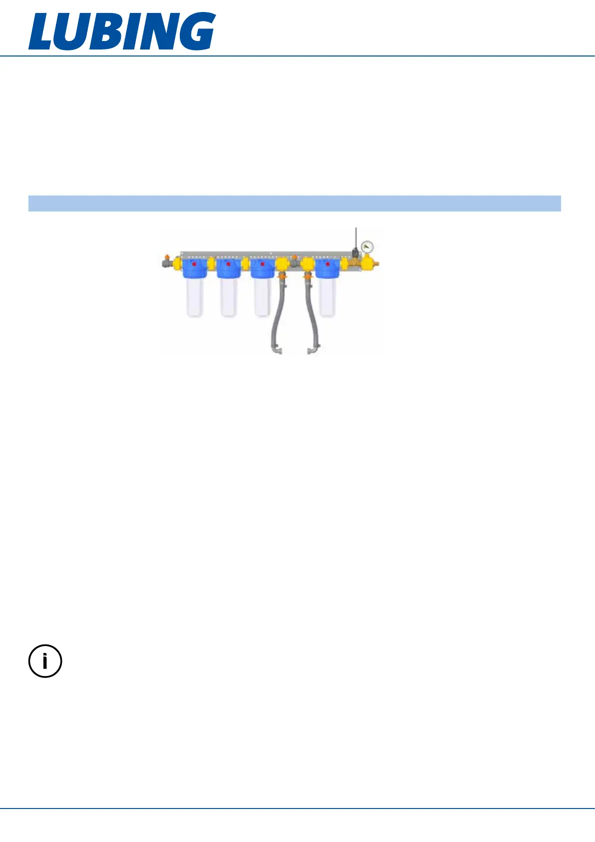
Example: art. 7126-V1-B
Further safety measures must be provided by the customer according to the valid regulations. As a general rule:
• The pump unit must be earthed.
• The power supply must be designed in accordance with Section 9 “Technische Daten/Technical data”.
• If a Vario pump unit is connected to a TT or TN network with a residual current circuit breaker, a universal
current-sensitive residual current circuit breaker type B with a leakage current of 300 mA must be used.
• To connect a Vario pump unit to an IT network, the jumper is set to CY=OFF. This, however, impairs the radio
interference suppression of the frequency inverter (see chapter 7 “Troubleshooting”).
The pump unit must not be connected to the power supply until “First start-up” (chapter 5.1)!
4.2 Installation of the water supply
Selection of the filter unit:
If a pump unit is connected directly, a lter unit with integrated main valve is required (the valve plug is connected
to the Touch Controller). A 1/2”-valve is sufcient for up to 25 l/min, a 3/4”- valve is required for more than 25 l/min.
A pressure gauge is installed behind the valve. While the pump is running, it must be ensured under all operating
conditions that the pressure at this pressure gauge (inlet pressure of the pump) is 1...4 bar. Filter units with bypass
can be used for the dosing of additives, in which any 3/4” dosing units can be installed. Usually lter units with 4
lters are used, only with very good water quality on site, lter units with only 2 lters can be used. The smallest
required ltration degree is 1 micron.
Mount the prefabricated lter battery horizontally on a wall or bracket near the pump unit.
Be sure to observe the installation direction! Filter sizes are pressed into the lter inserts (25 micron, 10 micron, 5
micron, 1 micron). The water must ow through the lter battery in this direction. This ensures optimum ltration of
the supply water and a long service life of the lter cartridges.
The supply line is connected to the input of the lter unit (3/4” IT). The supply line should at least correspond to the
diameter of the pump suction connection, preferably larger, and should be as free as possible of resistances and
throttling points. There is a hose connector at the outlet of the lter unit. Here the 3/4” hose of the pump unit (or a
hose to a tank) is connected. The hose must be laid in such a way that it is not bent too much and does not rub.
The valve connector cable is connected to the Touch Controller according to the “Wiring plans” (chapter 7). After
the connection, the manual shut-off valve can be opened and the lters can be put under water. Before switching
on the system, the lters need to be vented: Open the breather valves on the lter head until only water emerges.
When later replacing used lter cartridges, make sure that the O-ring is cleaned and lightly greased (e.g. with
Vaseline).
IMPORTANT INFORMATION
Make sure that the order of the lter cartridges is correct.
Check the condition of the lter cartridges regularly. If they are very dirty, replace them. Regular replacement
(e.g. once a year) is recommended. Dirty lters can lead to an insufcient inlet pressure below 1 bar.
When using a chem. lter cartridge (5 micron chem.), it must be replaced regularly (twice a year or after
150 m
3
ow).