Top climate system
with LUBING Touch Controller
Copyright © Lubing System - All rights reserved
18
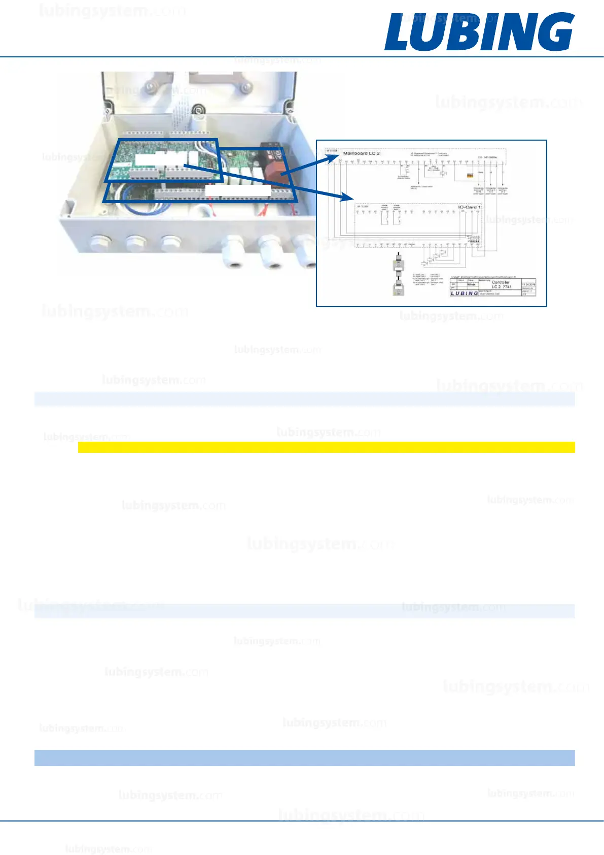
IO-Card
Mainboard
4.4.1 Connection of external climate computers and sensors
The correct pin assignment for external climate computers and sensors can be found in the wiring plans (see
chapter 7 “Wiring plans”).
External climate computer
The potential-free switching contact of an external climate computer is connected to the prescribed input terminals
of the controllers (e.g. DI1 and 24V for LC-1; see chapter 7 “Wiring plans”). These cables must be laid separately
and should be shielded. Only potential-free cables are allowed for connection. If the potential-free contact is closed
(24V are applied to the input), the system cools/humidies.
Sensors
Sensors are also connected to the input terminals. These cables must also be installed separately. The cables must
have a low resistance (1.5 mm
2
).
4.4.2 CAN connection
In the LCM vario version (art. 7745), the controller can be connected to extension boxes (art. 7750) if required.
Eight additional outputs are available for each box. The connection is made via CAN bus. The corresponding
mainboard and IO-Card terminals must be connected as shown in the wiring plans (see chapter 7 “Wiring plans”).
– The CAN connection must be looped through. Do not use stub lines!
– Jumper J12 must be plugged into the last extension box (terminating resistor).
– Only twisted pair cables may be used for the connection.
– For longer cables, we recommend using shielded cable.
– The addresses of the IO-Cards must be set with the DIP switches as shown in the wiring plans.
4.5 Installation of connecting pipes and nozzle lines
The pipes must rst be positioned with brackets or suspension material. Only then both the connecting pipes and
the nozzle pipes are connected with cutting ring ttings or alternatively with PressFix ttings.
CAUTION
To avoid malfunctions, lay all cables in the controller close to the base plate.
Never connect or disconnect components when the controller is switched on.
lubingsystem.com
lubingsystem.com
lubingsystem.com
lubingsystem.com
lubingsystem.com
lubingsystem.com
lubingsystem.com
lubingsystem.com
lubingsystem.com
lubingsystem.com
lubingsystem.com
lubingsystem.com
lubingsystem.com
lubingsystem.com
lubingsystem.com
lubingsystem.com
lubingsystem.com
lubingsystem.com
lubingsystem.com
lubingsystem.com
c
lubingsystem.com
lubingsystem.com