Top climate system
with LUBING Touch Controller
Copyright © Lubing System - All rights reserved
17
4.4 Installation LUBING Touch Controller
The LUBING Touch Controller should be installed in a dry, clean and easily accessible location near the pump
unit. For mounting, the cover must be opened and the housing is fastened with suitable screws through the holes
intended for xation.
The LUBING Touch Controller has a wide voltage input (85-264 V, 50/60 Hz). The voltage supply is usually made
via a multi-core connection cable of the pump unit and must usually be 220-240 V to supply the valves. Other
cables (e.g. from additional modules, pressure switches, climate computers, etc.) are also inserted into the Touch
Controller. Depending on the pump unit and the additional modules, the appropriate Touch Controller must be
selected (for pump units with frequency inverter, the “LCM vario” version is required).
The cables are connected according to the wiring plans (see chapter 7 “Wiring plans”).
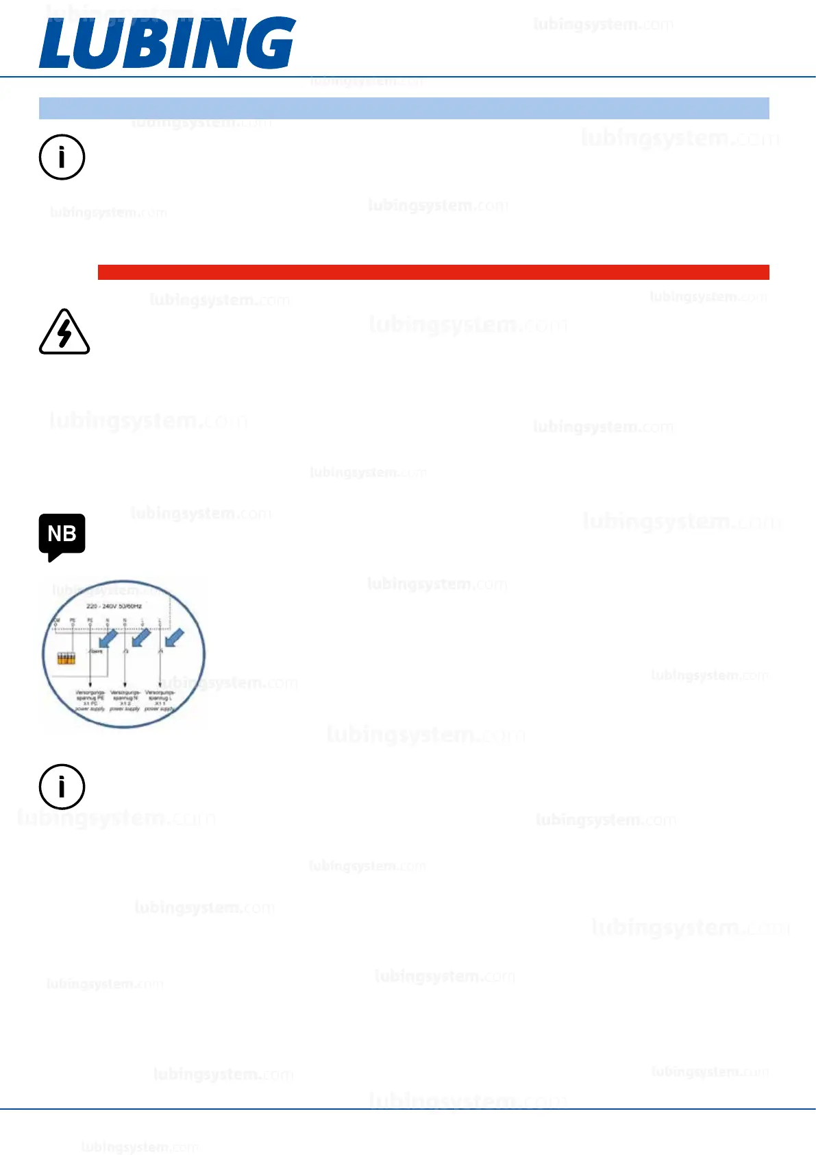
The multi-core cables of the pump unit are labelled with numbers. In the circuit
diagrams, the numbering is marked as shown in the adjacent detail. Coloured cables
are marked accordingly (abbreviations according to IEC 60757). GNYE (green/yellow)
identies the protective conductor. The protective conductors of all components must
be connected to each other!
IMPORTANT INFORMATION
The LUBING Touch Controller is essential for controlling the Top climate system. The manufacturer
accepts no liability for the installation of a system without the Touch Controller.
NOTE
Suitable cable glands must be used to ensure good sealing and strain relief of the cables.
DANGER!
Warning of electrical hazard!
Touching live parts or parts that have become live due faults, poses a direct risk of death. Damage to the
insulation or individual parts can be fatal hazard.
– Only electrical specialists are allowed to work on the system’s electrical equipment.
– When working in the electrical equipment always shut off the power and verify safe isolation.
– Observe the regulations of VDE (Verband der Elektrotechnik Elektronik Informationstechnik e.V.)
or IEC (International Electronical Commission) and the national accident prevention regulations for
electrical systems and equipment.
IMPORTANT INFORMATION
Make sure that the mainboard and the IO-Card are not confused when connecting the cables. Mainboard
and IO-Card are marked in the circuit diagrams. Attention: Sometimes there is the same name of the
terminals on both boards.
lubingsystem.com
lubingsystem.com
lubingsystem.com
lubingsystem.com
lubingsystem.com
lubingsystem.com
lubingsystem.com
lubingsystem.com
lubingsystem.com
lubingsystem.com
lubingsystem.com
lubingsystem.com
lubingsystem.com
lubingsystem.com
lubingsystem.com
lubingsystem.com
lubingsystem.com
lubingsystem.com
lubingsystem.com
lubingsystem.com
c
lubingsystem.com
lubingsystem.com