Top climate system
with LUBING Touch Controller
Copyright © Lubing System - All rights reserved
28
– commercially available disinfectants*/medicines can be used, but only up to a maximum dosage of 1%. A
suitable LUBING medicator or electrical doser can be used for the dosage. The position of the dosing unit is
before the last lter of the lter unit. Accordingly, a bypass for the lter units is available. LUBING mixers can
be used for predilution of the additives.
– the additive used must dissolve completely in water. For example, no crystals may form which could damage
the pump and clog the nozzles.
– the dosing should only be done for a short time in order to avoid permanent damage to the system.
– after disinfection/medication, the system must be thoroughly ushed with clear water for a few minutes. First
ush the pump and pipes with open ball valves at the pipe ends. In order to ush the nozzles thoroughly, the
ball valves should then be closed and ushed further.
*A list of the commercial usual disinfectants is e.g. at the “Deutsche Veterinärmedizinische Gesellschaft
(DVG) for the food range available (Frankfurter Str. 89, 35392 Gießen, - http://www.dvg.net ).
If additives are used frequently, HR components with increased resistance can be used for a longer lifetime.
Lubing accepts no liability for damage caused by the use of additives.
5.5 Operation pump system
The pump unit may only be supplied with cold water. The water temperature at the inlet must not exceed 40°C.
This applies in particular to operation with a minimum ow rate (min. number of nozzles). The water temperature
should not exceed 20°C when the water is supplied from a tank structure installed above the pump unit and
approved by Lubing.
The supply line to the pump should at least correspond to the specied diameter of the pump suction connection,
preferably larger, and should be as free as possible of resistances and throttling points. Low inlet pressure and
increased water temperature can cause cavitation and lead to a drastically shortened service life of the pump.
Make sure there are no leaks in the connections.
If the pump unit is pressure fed, a lter unit with integrated main valve must be used. A pressure gauge is installed
behind the valve. While the pump is running, it must be ensured under all op- erating conditions that the pressure
at this pressure gauge (inlet pressure of the pump) is 1...4bar.
Depending on the operating conditions, the crankcase might heat up to 60°C. Higher temperatures indicate
impermissible operating conditions or a fault in the pump unit.
Any deviations from the normal operating pressure indicate errors in the system. The fault does not have to be at
the pump, so the following should be checked rst:
– condition of the supply line (shut-off valves open, inlet pressure sufcient, ...);
– condition of pressure lines, nozzles, pressure control valve and pressure gauge.
Refer to chapter 7 “Troubleshooting” for further details.
The following descriptions concern components integrated in the pump unit.
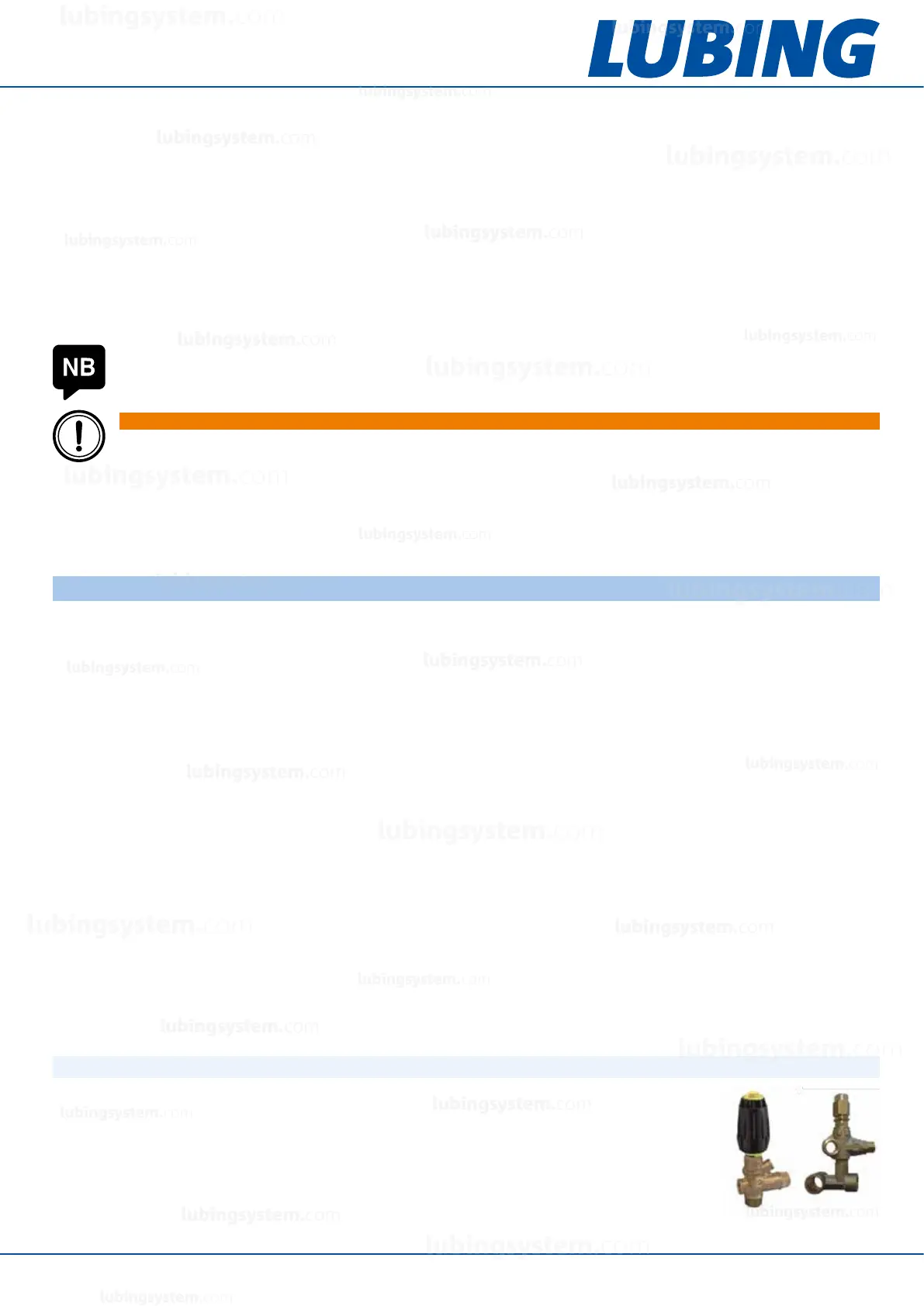
5.5.1 Pressure regulator/bypass valve
Plunger pumps are positive displacement pumps, i.e. they work against any pressure. A
pressure regulator or bypass valve is therefore absolutely necessary. It must be set so that
the nominal pressure cannot be exceeded by more than 7% (max. 75 bar) in the event of
a fault (outlet closed, no water consumption). The valves in the pump units are correctly
factory preset. No liability will be accepted if the setting is changed inadmissibly or if a
safety device is missing.
NOTE
Excluded are additives containing chlorine, as these can cause damage to the system components.
WARNING
When operating with aggressive, ammable, hazardous to health and the environment or media critical
due to other properties, a hazard must be prevented by suitable protective measures.
lubingsystem.com
lubingsystem.com
lubingsystem.com
lubingsystem.com
lubingsystem.com
lubingsystem.com
lubingsystem.com
lubingsystem.com
lubingsystem.com
lubingsystem.com
lubingsystem.com
lubingsystem.com
lubingsystem.com
lubingsystem.com
lubingsystem.com
lubingsystem.com
lubingsystem.com
lubingsystem.com
lubingsystem.com
lubingsystem.com
c
lubingsystem.com
lubingsystem.com