Top climate system
with LUBING Touch Controller
Copyright © Lubing System - All rights reserved
19
IMPORTANT INFORMATION
Make sure that no impurities or dirt get into the pipe system. This will ensure that the nozzles will work
properly later on.
4.5.1 Positioning and orientation of nozzle lines
The following details are recommendations which have often proven themselves in practice. Depending on the
ambient conditions (air ow, barn equipment, etc.), the optimum installation of the nozzle lines may differ from the
recommendations.
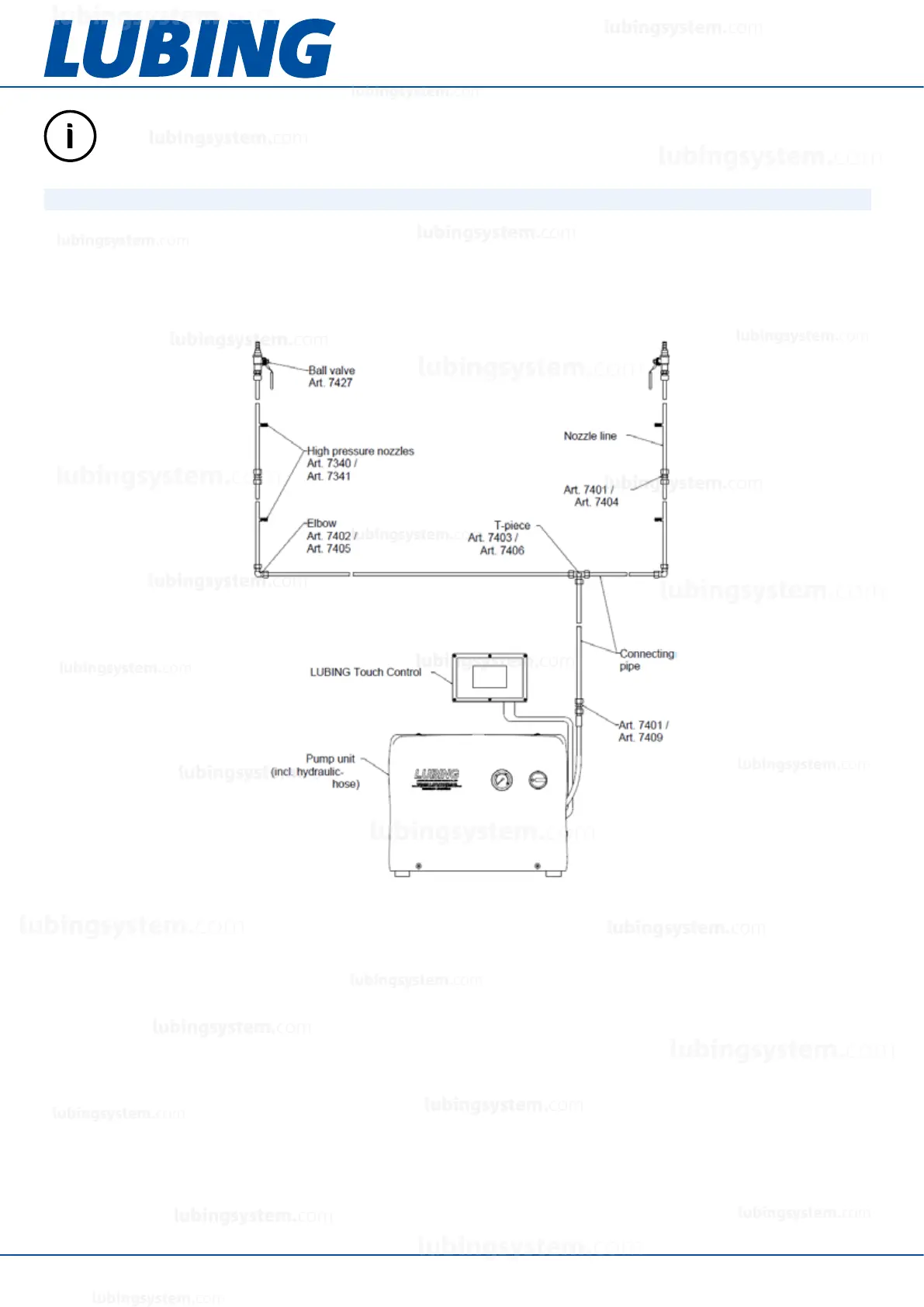
The following illustration shows in principle a possible arrangement of the components in a system. In addition
there are components in the supply line to the pump unit (lter unit etc.). The ball valves at the ends of the lines can
be opened for ushing and venting.
Depending on the size of the barn and the ventilation system, the layout of the nozzle lines is determined. Generally
applies:
– the nozzles should not spray against the air ow.
– the minimum distance to the ceiling of at least 0.5m should be maintained.
– there should be a free space of at least 3m in the spraying direction of the nozzle. In case of obstacles in this
free space, these adapters can be closed with plugs (Art. 7326).
– the line lengths should be kept as short as possible to minimize pressure losses (espe cially with high ow
rates!).
The following sketches show examples of possible layouts:
lubingsystem.com
lubingsystem.com
lubingsystem.com
lubingsystem.com
lubingsystem.com
lubingsystem.com
lubingsystem.com
lubingsystem.com
lubingsystem.com
lubingsystem.com
lubingsystem.com
lubingsystem.com
lubingsystem.com
lubingsystem.com
lubingsystem.com
lubingsystem.com
lubingsystem.com
lubingsystem.com
lubingsystem.com
lubingsystem.com
c
lubingsystem.com
lubingsystem.com