LX 10k
Advanced operation
Document name: LX 10KUM
Document revision: R1
helping him center.
A glider represents the pilot’s current position in the thermal. The glider can be either on the
left side (circling to the right), or the right side (circling to the left) of the Wind indicator.
Next we see dots forming a circle, at 18 degree intervals. These dots represent discretized
parts of the thermal. The dots are either red or blue. Red indicates a lifting par t of the thermal
and blue a sinking part. The size of the dot indicates the intensity, larger dots representing
greater vertical speeds, in either direction. A single dot (white when dark theme is used and
white with black outline when light theme is used) represents the strongest part of the thermal
during your last circle.
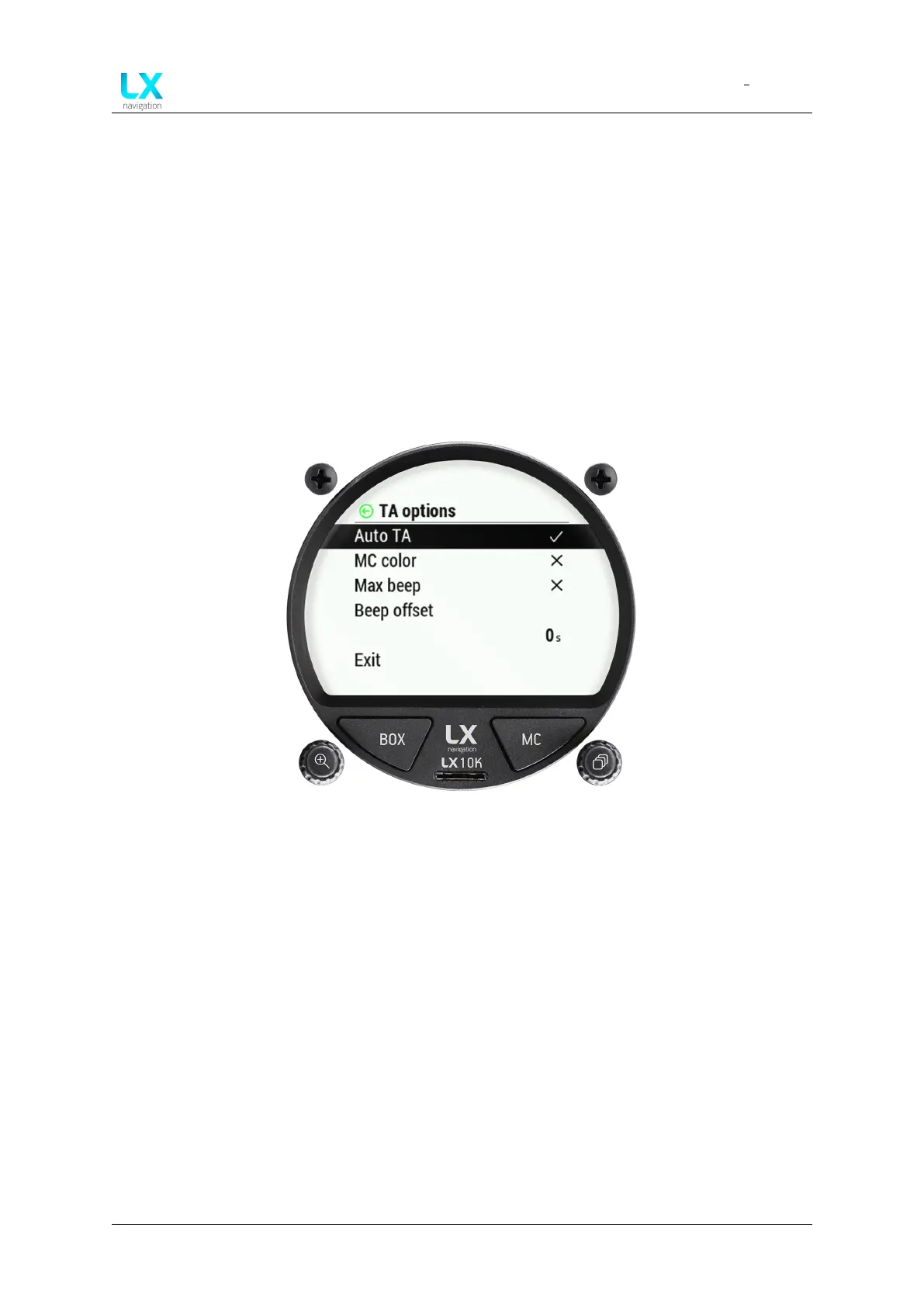
Figure 35. TA options overview
Pressing the right push-rotary knob will open the TA options page. Here, we can choose to turn
on different functions, such as:
• Auto TA - Ticking this option will make the LX 10k turn to TA page when it detects circling
has started. Once the LX 10k detects it is no longer circling, it will revert back to the page
you had before.
• MC color - When MC color scheme is ticked, red dots represent climb which is stronger
than 1.2*MC value set. Yellow dots represent climb in range of 0.8*MC and 1.2*MC value
set. Blue dots represent climb less than 0.8*MC value. If MC setting is less than 0.5m/s,
default color scheme is used.
• Max beep - The device beeps when you are passing through the point at which the maxi-
mum thermal strength was recorded in your last turn.
• Beep offset - Offsets the beep by a set amount of seconds.
Device manual Public 39