UNLOADING AND ASSEMBLY
169001 Revision E
26
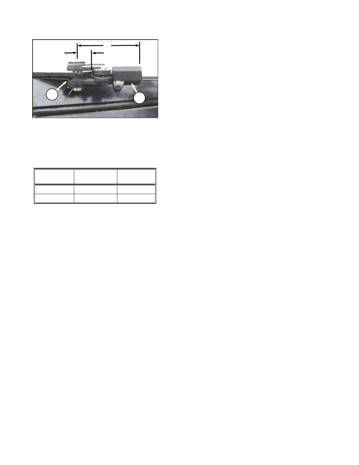
i. Rotate cylinder rod with wrench on stroke
control (G) to dimension ‘Y’ in following table.
j. Tighten clamping bolt on clevis (C).
k. Loosen clamping bolt on stroke control (G), and
rotate stroke control to dimension ‘X’ in the
following table:
MODEL
DIM. ‘X’
in. (mm)
DIM. ‘Y’
in. (mm)
14 FT 8.70 (221) 1.97 (50)
16 and 18 FT 8.23 (209) 2.48 (63)
l. Tighten clamping bolt to 65 ft·lbf (90 N·m).
NOTE
Dimensions ‘X’ and ‘Y’ may require
additional adjustments to obtain correct
tracking of unit to suit field conditions.
Each turn of the stroke control
changes the tracking by approximately
2 in. (51 mm).
X
Y