a. Full FLD Current (A6) less than or equal to 20
a. Vbus / 2 must be greater than or equal to (Vf x 1.5)
b. Full FLD Current (A6) greater than 20
a. Vbus / 4 must be greater than or equal to (Vf x 1.5)
If either of these conditions are not true then the standard field module must be used
5. Input voltage requirements.
These are the two equations to calculate to determine the minimum AC voltage applied to the
drive based on the conditions;
‐ Rated drive amps is the current rating of the Quattro
DC drive 125, 150, 200, 250, 300.
‐ Full Load Motor Volts is the required voltage to run at
contract speed up at full load. If this isn’t know use the
motor nameplate volts.
a. V L-L = (((Full Load Motor Voltage X 1.3) – 75) / 1.41)
Equation 1. Nominal Line to Line voltage
b. V L-L = ((Rated motor current X Full Load Motor voltage x 0.92) / rated
drive amps)
Equation 2. Nominal Line to Line voltage
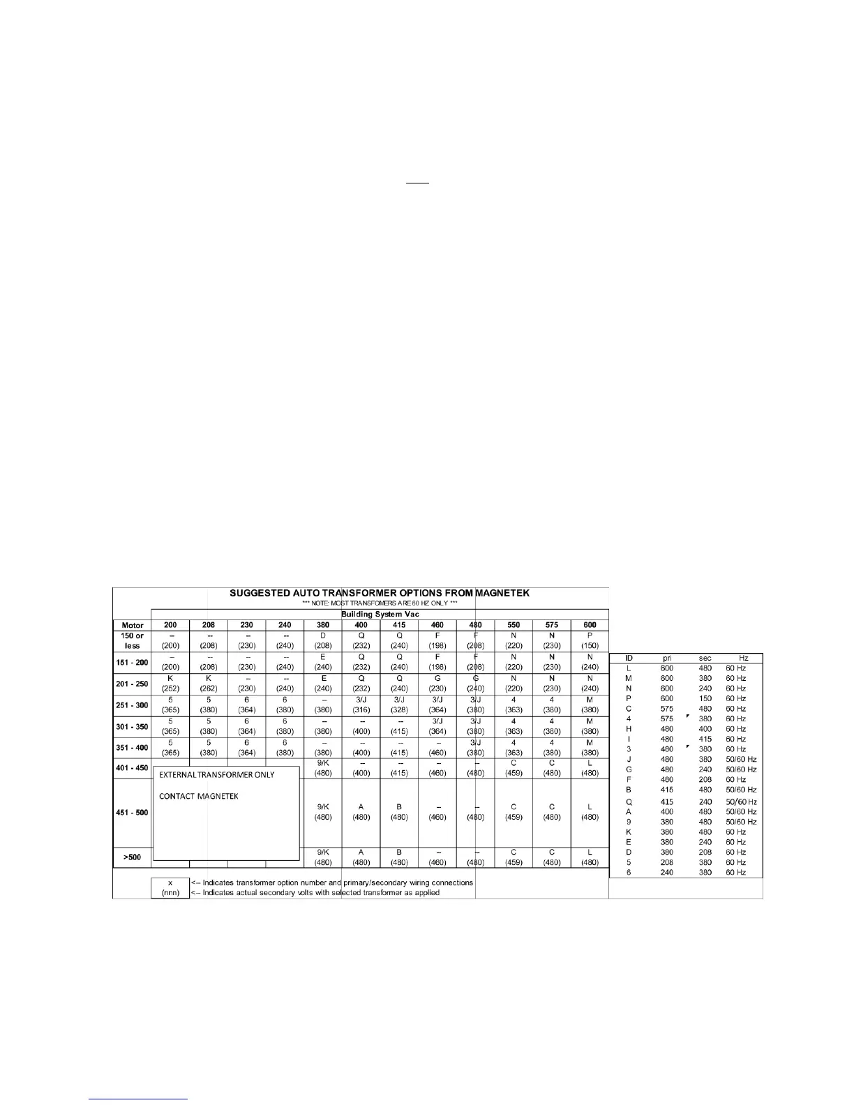
The drive will require the larger of the values from Equation 1 and 2. This determines
minimum voltage required to operate that motor. If the actual voltage is less than this calculation, then
it would be required that the voltage be stepped up. Magnetek has optional Auto transformers
specifically designed for this purpose and will fit within the Quattro drive enclosure. If the actual
voltage applied to the Quattro exceeds 1.5 x rated motor voltage, then it would be recommended that
the voltage be stepped down to closer to 1 to 1.1 times rated motor voltage. The chart shown below
provides a method to select an auto transformer.
6. Open the fuse holders in the drive labeled F1, 2, 3, 4
7. Apply three phase power to the drive, measure the 230V control power on the line side of F1,
F2. This should be between 220 and 240Vac.
8. Turn off the three phase power and close the F1, F2 fuse holders. Re-apply the three phase
power. Locate the LV Power Distribution PCB (A10), verify the low voltage DC levels;