Quattro DC Analog Outputs C4 Submenu
83
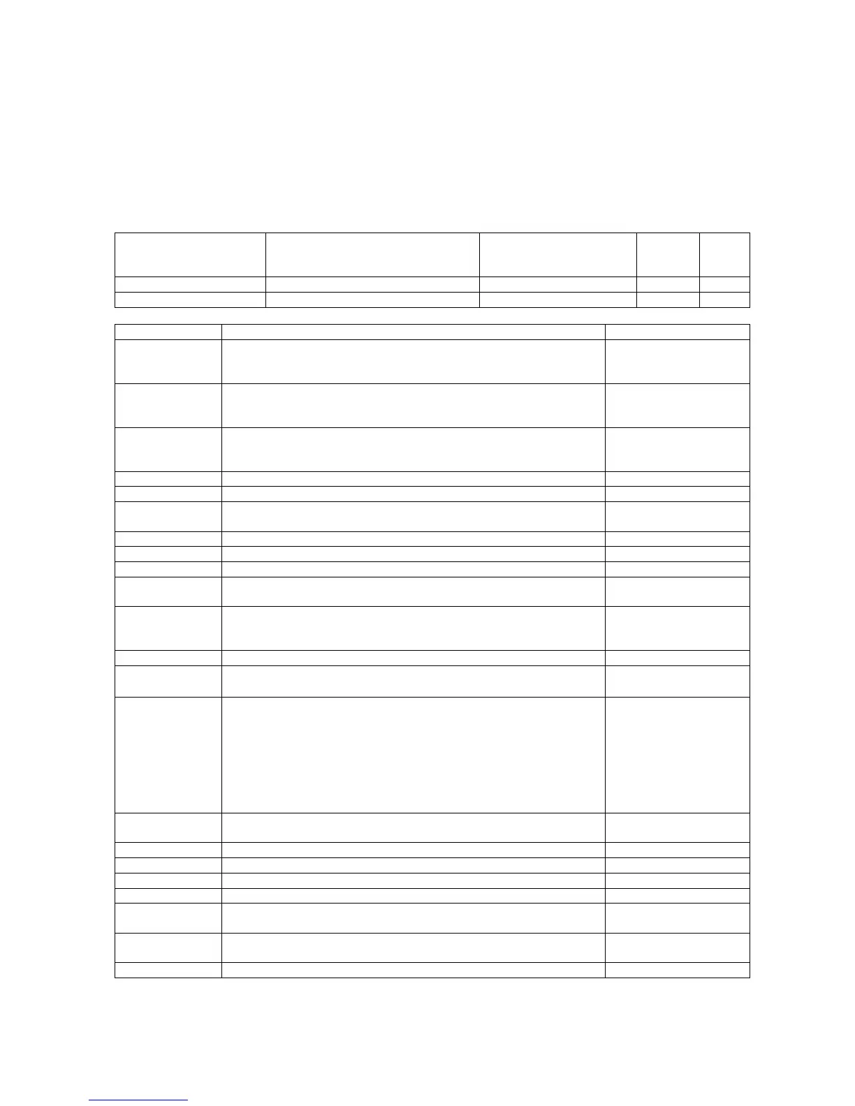
Analog Outputs C4 submenu
With a gain of 1.0 and an offset of 0.0, 10V will
indicate 100% or full value based on
programmed values. For example, with the
above scenario of a gain of 1.0 and an offset of
0.0, a 10V signal an Analog Output set to arm
current would indicate 100% of rated current.
Whereas a 0V signal on the same Analog
Output would indicate 0% of rated current.
Any value over 100% will cause the analog
channel to saturate.
Parameter Description Default
Hidden
Item
Run
lock
out
ANALOG OUTPUT 1
analog output #1 SPEED REF Y N
ANALOG OUTPUT 2
analog output #2 SPEED FEEDBK Y N
choices description D/A units
analog addr2
(Analog Address 2) Ability to view hex monitor functions via the
analog outputs. Choosing this function will display the hex monitor
value of ADDR2& (U8).
none
analog addr3
(Analog Address 3) Ability to view hex monitor functions via the
analog outputs. Choosing this function will display the hex monitor
value of ADDR3& (U8).
none
arb state
(ARB State) Ability to view which section ARB Mode is in while
setting up ARB. For further information, see Anti-Rollback on page
125.
-
arm current (Motor Armature Current) Measured motor armature current % rated current
arm voltage (Motor Armature Voltage) Measured motor armature voltage % of rated volts
aux torq cmd
(Auxiliary Torque Command) Additional torque command from
auxiliary source
% rated torque
bus voltage (DC Bus Voltage Output) Measured DC bus voltage % of peak in
est motor spd (Estimated Motor Speed) Estimated speed of the motor RPM
field current (Motor Field Current) Measured motor field current % of rated (Full Field)
iarm error
(Armature Current Error) Measures the difference between the
reference current and the measured current
Amps
ls pwr input
(Line Side Power Input) Estimated power transfer to and from the
AC Line. Value is positive when drive is pulling power from the line
and negative when drive is delivering power back to the line.
kW
pretorque ref (PreTorque Reference) Pre-torque reference % base torque
Motor overload
0 – 10V, when the number reaches 10V the drive will shut down
and declare the fault.
0 – 100%
motor mode
(Motor Mode) Voltage level switches to indicate the mode the
current regulator is operating in.
1) Forward motoring (~ 9.7V)
2) Forward regeneration (high CEMF) (~ 4.4V)
3) Forward plugging (regeneration at low CEMF) (~ 1.3V)
4) Reverse plugging (regeneration at low CEMF) (~ -1.3V)
5) Reverse regeneration (high CEMF) (~ -9.7V)
6) Reverse motoring (~ -4.4V)
-
spd rg tq cmd
(Speed Regulator Torque Command) Torque command from
speed regulator
% base torque
speed command (Speed Command) Speed command before S-Curve % rated speed
speed error (Speed Error) Speed reference minus speed feedback % rated speed
speed feedbk (Speed Feedback) Speed feedback used by speed regulator % rated speed
speed ref (Speed Reference) Speed reference after S-Curve % rated speed
tach rate cmd
(Tachometer Rate Command) Torque command from tach rate
gain function
% base torque
tach speed
(Tachometer / Encoder Speed) Bi-directional signal representing
velocity measured by the encoder.
ft/min or m/sec
torque ref (Torque Reference) Torque reference used by vector control % base torque
Table 14: Analog Outputs C4 Submenu