Quattro DC Drive A1 Submenu
48
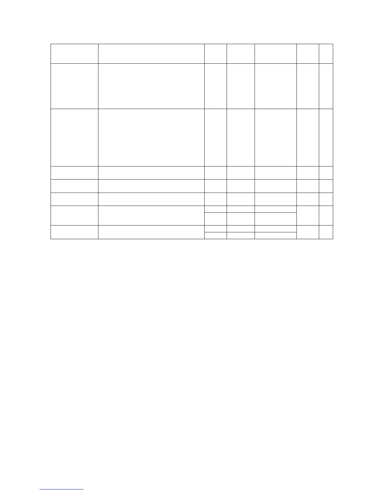
Parameter Description Units Default Range
Hidden
Item
Run
lock
out
DSPR TIME
(Drive Standby Power Reduction Time)
Determines how long the drive will remain
energized with motor field current at
Standby amps before progressing to
complete drive shutdown and utility side
disconnection. Only used when DPSR
ENABLE (C1) is set to ENABLE
min 10 0 – 546
Y Y
FullFldFaultTime
(Full Field Fault Time) Determines
the maximum time the drive can
remain at Full Field without actually
running. If logically held in that
condition for longer than the Full field
Time, a Fault will be declared to
prevent potential burnout of the
motor field.
min 1 0 - 99
Y Y
SER RES CRP
TIME
Maximum time to allow rescue operation
Sec 180 0 - 200
N Y
SER2 FLT TOL
Maximum time to allow between
reception of packets in serial mode 2
Sec 0.5 0 - 200
N Y
SER2 Insp spd
Used to select speed during inspection
mode
ft/min 30 0 - 100
N Y
SER2 Insp spd
SER2 RS CRP
spd
Used to select speed during inspection
mode
Used to select speed during rescue mode
m/sec 0.150 0
0.50
N
N
Y
Y
ft/min 10 0 - 300
SER2 RS CRP
spd
Used to select speed during rescue mode
m/sec 0.050 0
1.54
N Y
Table 1: Drive A1 Submenu
Detailed descriptions
HI/LO Gain
When HI/LO GAIN SRC (C1) is set to internal,
GAIN CHG LVL (A1) sets the speed reference
level that controls the Hi/Lo gain switch. The
velocity regulator will use normal ‘high gain’
when the reference speed is below this value,
or ‘low gain’ settings when the speed reference
is above this value.
On some elevators when the speed response
(gain) is set to high levels as required for good
velocity tracking during acceleration, the
resonant characteristics of the elevator ropes
can cause car vibration while running at steady
state speed. To reduce this problem, the
response (gain) of the speed regulator is
effectively reduced to a lower value so that the
resonant characteristics of the ropes are not
continuously excited. The High/Low gain
switch modifies the response of the speed
regulator via the gain reduce multiplier.
GAIN REDUCE MULT (A1) adjusts how much
gain reduction will occur at higher speeds.
High / low gain switching may be controlled
either externally or internally. The high / low
gain source parameter (HI/LO GAIN SRC) in
Configuration menu C0 allows for an external
or automatic internal gain switch selection.