IMPULSE•T Instruction Manual - October 2015
3-6
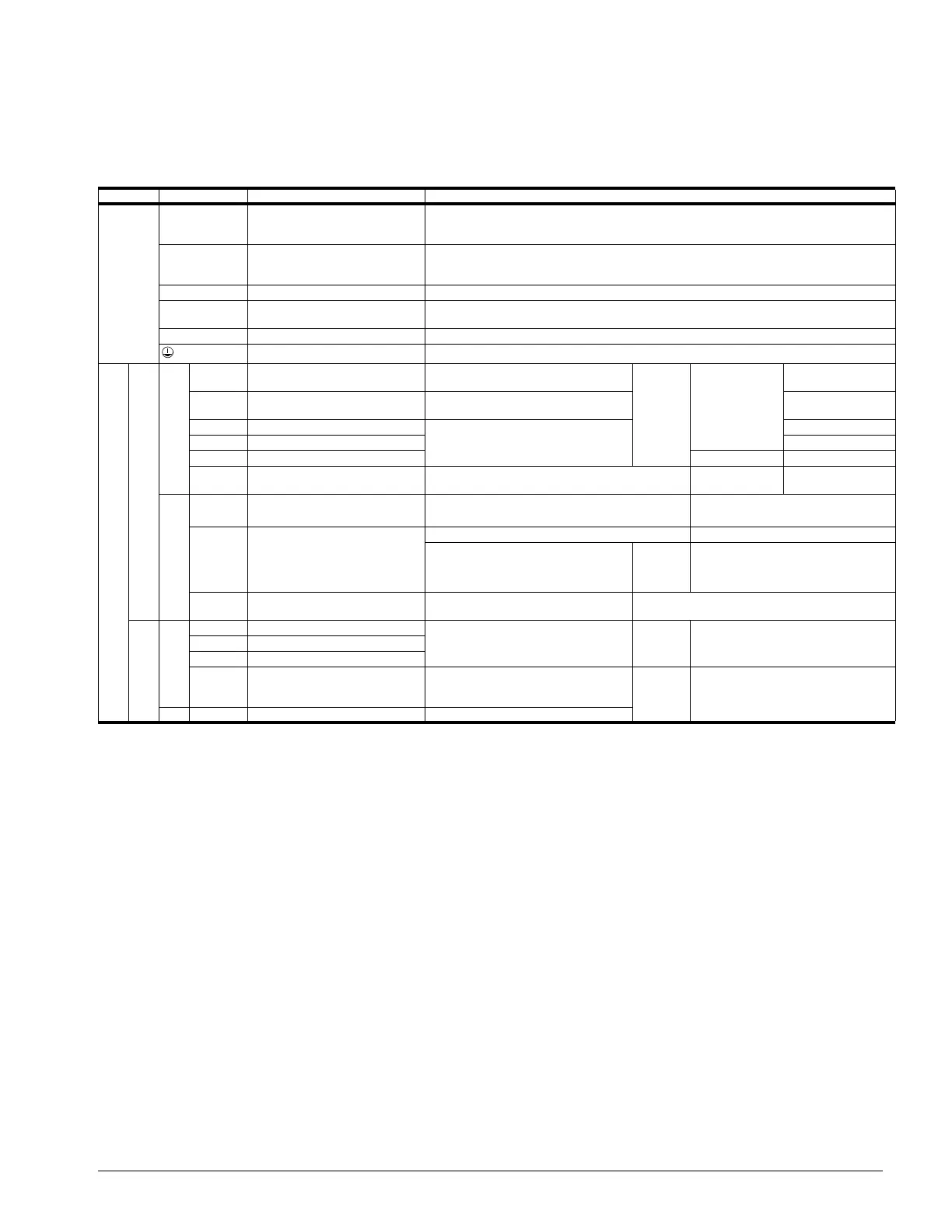
Terminal Description
Table 3-1: Control Circuit Terminals
Type Terminal Name Function (Signal Level)
Main Circuit
R/L1,
S/L2,
T/L3
AC power supply input AC power supply input
U/T1,
V/T2,
W/T3
Inverter output Inverter output
B1, B2 Braking resistor connection Braking resistor connection
+2, +1 DC reactor connection
When connecting optional DC reactor, remove the main circuit short-circuit bar
between +2 and +1.
+1, (–) DC power supply input DC power supply input (+1: positive; (–): negative)
Grounding Ground to local grounding codes
Control Circuit
Input
Sequence
S1 Multi-function input selection 1
FWD run when closed, stop when
open
H1-01–
H1-05
120 VAC ±10%
S2 Multi-function input selection 2
REV run when closed, stop when
open
S3 Multi-function input selection 3
Inputs are programmableS4 Multi-function input selection 4
S5 Multi-function input selection 5
X2*
Multi-function input selection
common
Common for control signal
Analog Input Signal
+V
+10.5 VDC
Power supply output
For analog command +10 V power supply
+10 V (Allowable current 20 mA
max)
A1 Master frequency reference
0 to +10 V/0 to 100% 0 to +10 V/(2K Ohm)
4 to 20 mA/0 to 100%
0 to 10 V/0 to 100%
0 to 20 mA/0 to 100%
H3-01
4 to 20 mA (250 Ohm), 0 to +10V/
(2k Ohm)
AC Frequency reference common 0V
0 to ±10V. Max ±5%
2 mA or less
Output
Multi-function
contact output
MA NO contact output
Factory setting: brake output H2-01
Dry contact capability:
250 VAC 1 A or less,
30 VDC 1 A or less
MB NC contact output
MC Contact output common
AM Analog monitor output
Factory setting: output frequency 0
to +10 V
H4-01
+10 VDC, 2 mA or less, 8-bit
resolution
AC Analog monitor common 0 V
* SC when the 24 VDC input option is used.
 Loading...