21
3.3. HYDRAULIC INSTALLATION
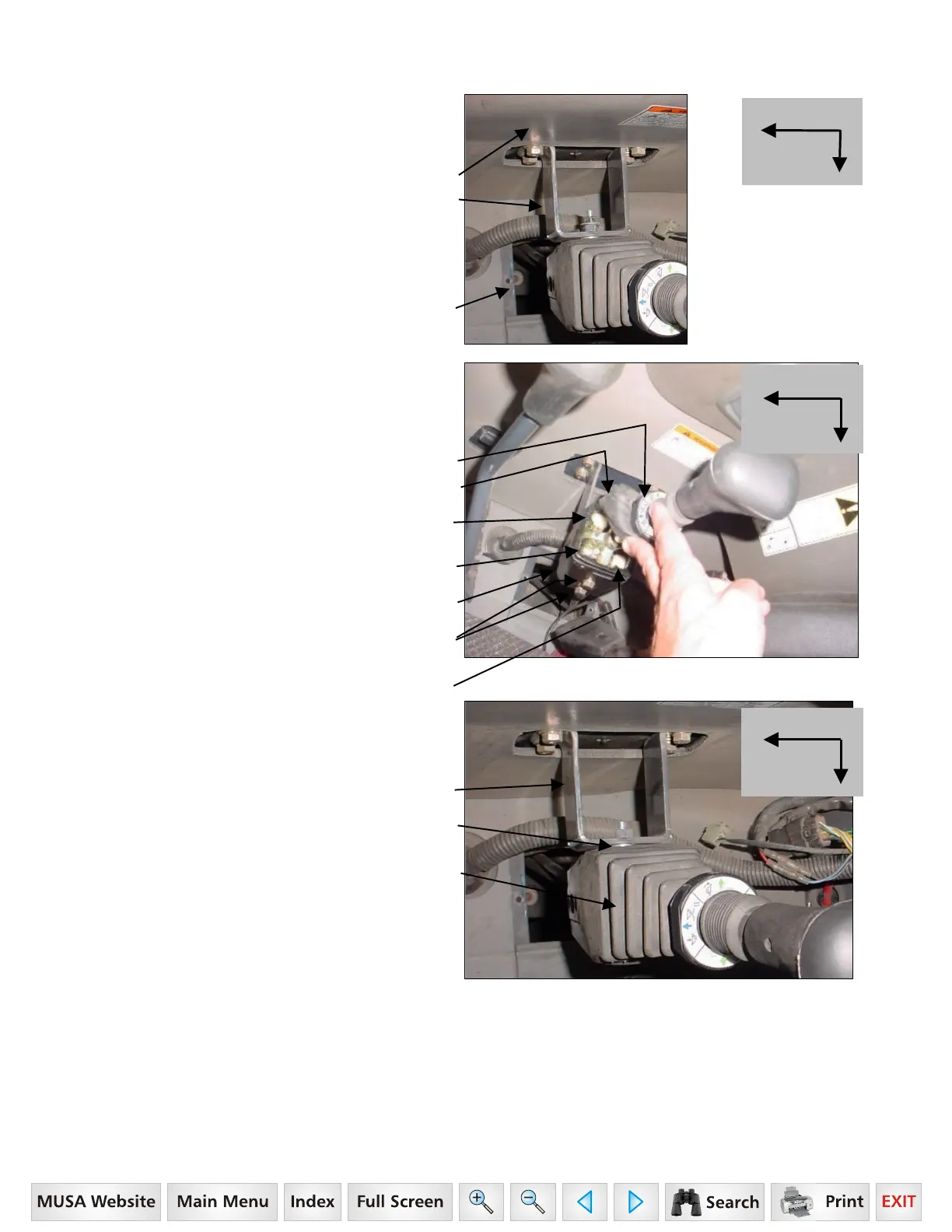
3.3.1. Remove RH cab console components to reveal
existing console bracket. Save console components
and console hardware.
RH Cab Wall
Existing Console Bracket
(installed on tractor).
3.3.2. Remove RH cab floor plate cover to reveal
opening to outside of cab. Save floor hardware.
Cab Floor Opening.
3.3.3. Peel rubber boot back from controller to
expose controller linkage. Position single lever
controller with cables so solid post is positioned
toward front and center of tractor.
Float part of decal faces toward front of tractor.
Rubber Boot, in raised position.
Lift Cable controls Raise & Lift
functions of Loader.
Solid post positioned toward
front and center of tractor.
Single Lever Controller.
8mm x 80mm Hex Bolt Grade 10.9 and
5/16" Lockwasher, 2 places.
Tilt Cable controls Dump & Rollback
functions of Attachment.
3.3.4. Install single lever controller to existing console
bracket using 8mm x 80mm hex bolts Grade 10.9
and 5/16" Lockwashers.
Existing Console Bracket
Two 5/16" spacer flatwashers
on top bolt only.
Single Level Controller
with pre-assembled Cables.
Front of Tracto
Center
of Cab
Front of Tracto
Center
of Cab
Front of Tracto
Center
of Cab
 Loading...