53
Maxuum III Digital Electronic Indicator 2239028 Rev D
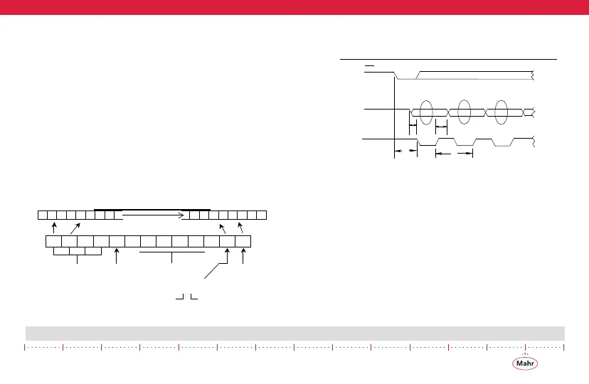
8.4 Theory of Operation
Enabling the data request line (SREQ\, pin # 4) will activate data
transmission. The SREQ\ input is falling edge triggered and
active low, it must go from high to low and held low until data
transmission starts, then it can be brought high. A single output
data reading comprises 13 digits (d1 - d13) with each digit
being 4 bits
long for a total of 52 bits for each message. The bit order for
each BCD digit is LSB to MSB. Data is valid during the low clock
pulse and during either clock transition (from low/high or high/
low). One display value is transmitted for each SREQ\ received.
There is a one clock delay between each BCD digit.
8.4.1 Digimatic Data Format
8.4.1.1 Timing Diagram for Digimatic Data Transfer
Method
b0 b1
b2
b3 b0
b1 b2
b3
b0 b1
b2
b3
b0 b1
b2 b3
d1
d2
d3 d4
d5
d6
d7
d8 d9
d10
d11
d12
d13
ALL "F"
SIGN
0 = +
8 = -
MSD LSD
MEASUREMENTS
UNITS
0 = mm
8 = inch
mm dp
DECIMAL POINT
X . X . X X X X
in d
TIMING DIAGRAM FOR DIGIMATIC DATA TRANSFER METHOD
T1 = 90 μs (min), T2 = 124 μs, T3 = < 62.5 ms, T4 = 428 μs
For 4 bits / digit is: 2.14 μsec
For 13 digits / reading is: 27.8 μsec
T4
VALID DATA
VALID DATA
VALID DATA
 Loading...