54
Maxuum III Digital Electronic Indicator 2239028 Rev D
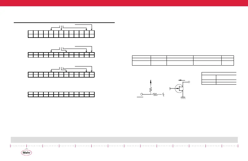
8.4.1.2 BCD Encoded Data Format
8.4.2 Electrical Characteristics
There are two types of hardware data communications signals
associated with the Maxum III Digimatic output, one is the input
type and the other is the output type. To establish a logic level
with the input type, be it logic high or logic low the external cir-
cuitry must be an open drain or an open collector type of driver.
Internally the input type is at logic high via a pull up resistor to
Vcc. To establish an output logic level with the output type, the
external circuitry must provide a pull up resistor to external
equipment Vcc.
8.5 Mating Connectors
EXAMPLES OF BCD ENCODED DATA FORMAT
EXAMPLE: + 1 . 2 3 4 5 mm
d1 d2 d3 d4 d5 d6 d7 d8 d9 d10 d11 d12 d13
FFFF00 1234540
EXAMPLE: - 0 . 3 4 9 mm
d1 d2 d3 d4 d5 d6 d7 d8 d9 d10 d11 d12 d13
FFFF80 0034940
EXAMPLE: - 0 . 1 9 7 5 in
d1 d2 d3 d4 d5 d6 d7 d8 d9 d10 d11 d12 d13
FFFF80 01975
51
EXAMPLE: OFF - SCALE CONDITION
d1 d2 d3 d4 d5 d6 d7 d8 d9 d10 d11 d12 d13
FFFF8/0FFFFFF5/41/0
BCD: Off-Scale Note:
All BCD digit fields will be set to 'F'. The sign, decimal point, and unit fields are encoded normally.
PARAMETER PIN # TEST CONDITION MAX RATINGS UNITS
input 4 Vi (max) 7.0 V
output 2, 3
Vo (max)
I (max)
7.0
1.0
V
mA
6pin
10 pin
R1
R2
Vcc
).054490%
/54054490%
open drain
output
Vi(max)
SREQ
SCLK
i(max)
SDAT
Vo(max)
 Loading...