13
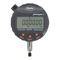
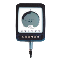
Maxuum III Digital Electronic Indicator 2239028 Rev D
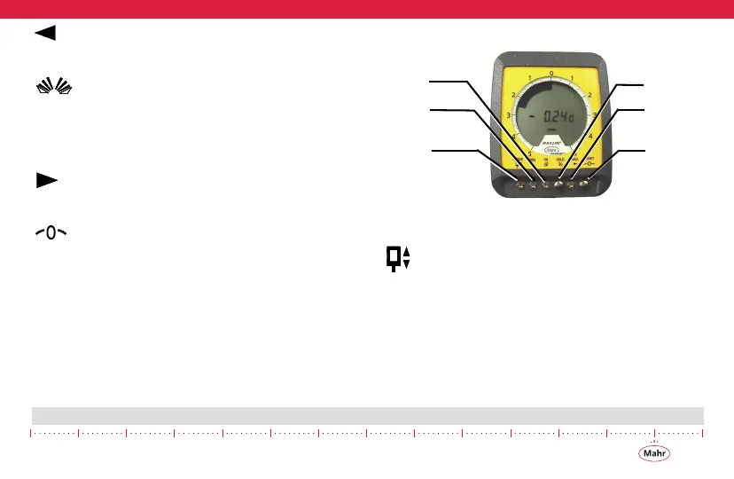
Left Tolerance Limit
Sets the left arrow at desired limit.
Display Switches
Indexes the digital readout and analog display clockwise (right-
handed switch) or counterclockwise (left-hand switch). The dis-
play switches will function only when the Indicator or Indicating
Unit is in the Auto-Zero (gaging) mode.
Right Tolerance
Sets the right arrow at desired limit.
RESET
To electronically set both the analog display and digital readout
to zero.
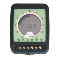
2.1.2 Controls - Enhanced Mode
Figure 3
MODE
Shows the real time static measurement of the spindle in the
indicator's measuring range while in Enhanced Mode (see Sec-
tion, ’4.2 Enhanced Mode’ on page 28). When the mode but-
ton is used to activate the Enhanced function the indicator's
analog display changes to the alternate mode, i.e. a normal Fan
display changes to a Single Element display, and dynamic but-
ton functions become active.
 Loading...