20
WORKING INSTALLATION
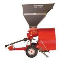
After executed length corrections, pro-
ceed to the denitive working installation:
1. Lubricate the telescopic section “A”
Fig 23.
2. Assamble metallic sections and pro-
tections.
3. Set the ends of the PTO shft at:
a) The imput shaft of the machine,
verifying proper installation of
the lock “B” Fig. 23.
b) The tractor, verifying the correct
coupling of the lock “C”.
4. Verify the protections “D” turn freely.
5. Then attach the safety chains to prevent spinning during work, with enough clearence perform normal
movements.
6. Lubricate the grease nipples “E” Fig. 23 according to the plan indicated at the Lubrication Plan on this
manual.
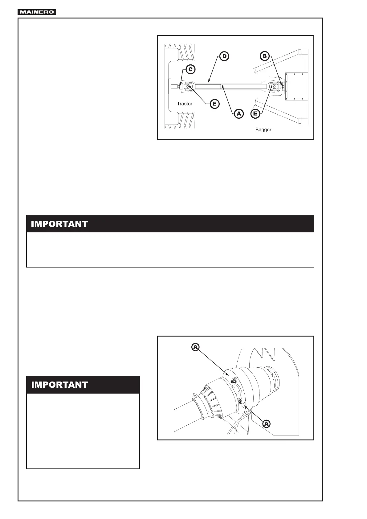
SHEAR BOLT
The PTO Shaft has installed one shear bolt
“A” Fig. 24, which act when any overload
at the auger exists.
The bolt used is:
For PTO Shaft B & P
Hexagon head bolt. Gº 8.8
RM 8 x 45 mm. . . . . . . . . 21705-346
- The PTO shaft demands to the operator “MAXIMUM” caution during work.
- Check at those tractors which posses protections at the zone were the PTO shaft is coupled, it does
not interfere normal function during work.
- Make sure when assembling the shaft that it “DO NOT” moves axially on the shaft.
FIG.23
FIG.24
Always use the bolt size and quality
stated, do not use a higher quality or
larger size because can affect the par-
ts to be powered.
If the shear bolt gets cut, identify the
cause for which this happened, and
solve the inconvenience before restart
the work.