18
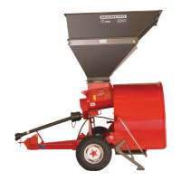
TONGUE REGULATION
Correct the height of the hitch “A” Fig. 18
at the working tongue, so that the chassis
is leveled respect the ground.
For this locate the rack to a height H:
25-30 cm Fig. 18 from the oor and the
roof of the tunnel parallel to the ground.
Register from the hitch “A” in function of
the height of the tractor draw bar. Adjust
correctly all the bolts “B” Fig. 18.
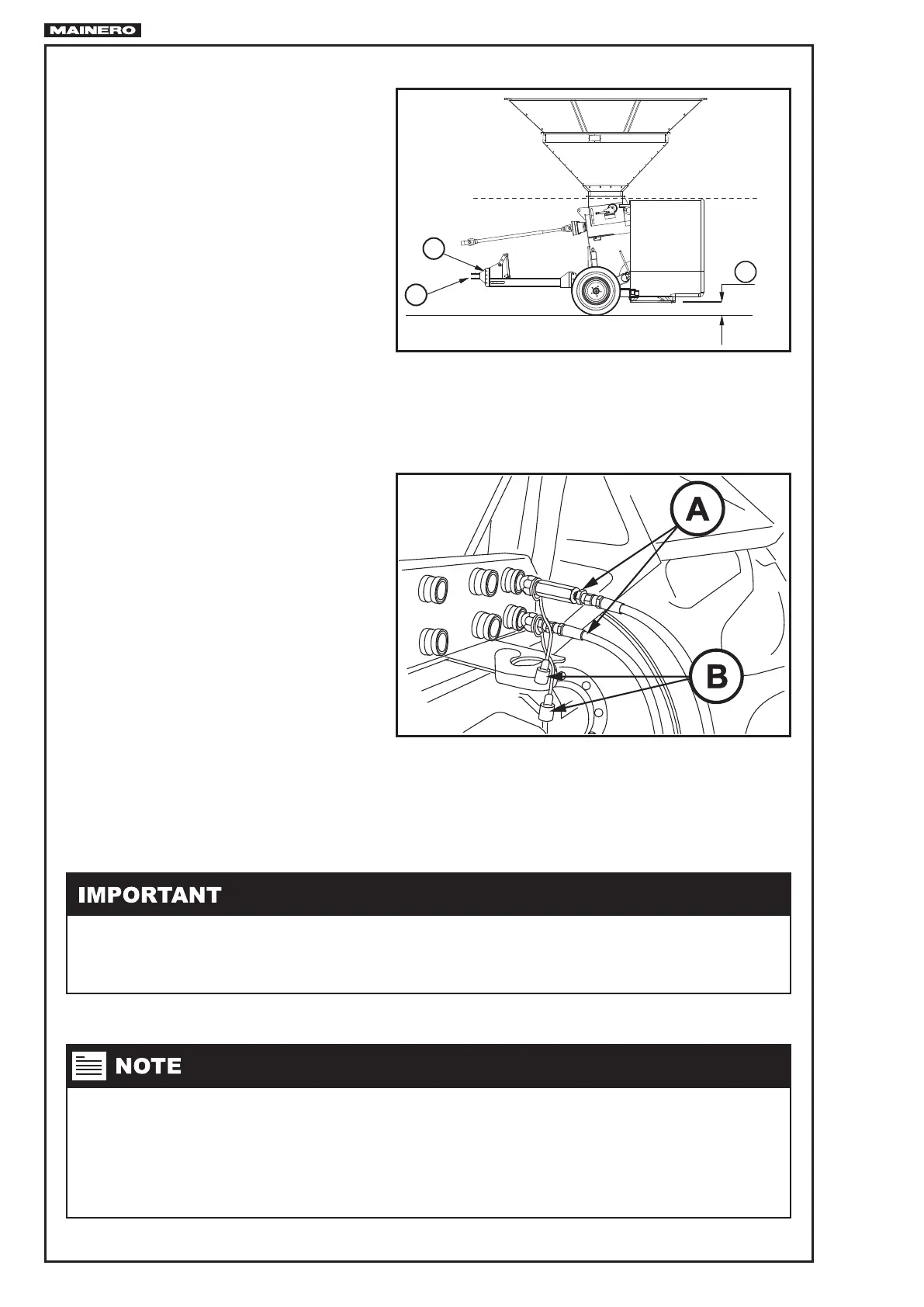
HYDRAULIC HOSES
The machine is equipped with two
hydraulic hoses of Ø ¼”, to raise or lo-
wer the working or transport height. They
have installed in its end, universal quick
coupling (male) “A” Fig. 19 of 1/2” NPT.
It has a spherical valvbe for blocking the
hydraulic circuit and tus be able to relea-
se pressure for coupling or uncoupling the
hoses.
• Before coupling, stop the tractor engi-
ne and release pressure of the hydrau-
lic circuit acting the lever in two directio-
ns, remove the caps “B” and clean the
quick coupling (male), as well as the
female terminals of the tractor.
• Before uncoupling, close the spherical valve to block the circuit. Stop the tractor engine and re-
lease pressure of the hydraulic circuit acting the lever in two directions. Then uncouple and put the
caps “B” Fig. 19.
A
B
H
Once coupled the hoses, verify:
1. That the machine can do normal movements without they get tight.
2. They do not have to be left too long to avoid accidents.
• We advise when coupling the hoses, chose its position, to coordinate the movements of the tractor
lever with those of the machine and identify the trip, in order that in successive couplings operate
the same way.
• Control that hydraulic hoses are not chipped or marked, in case of being, replace them immediatly.
FIG.18
FIG.19