17
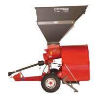
FIG.16
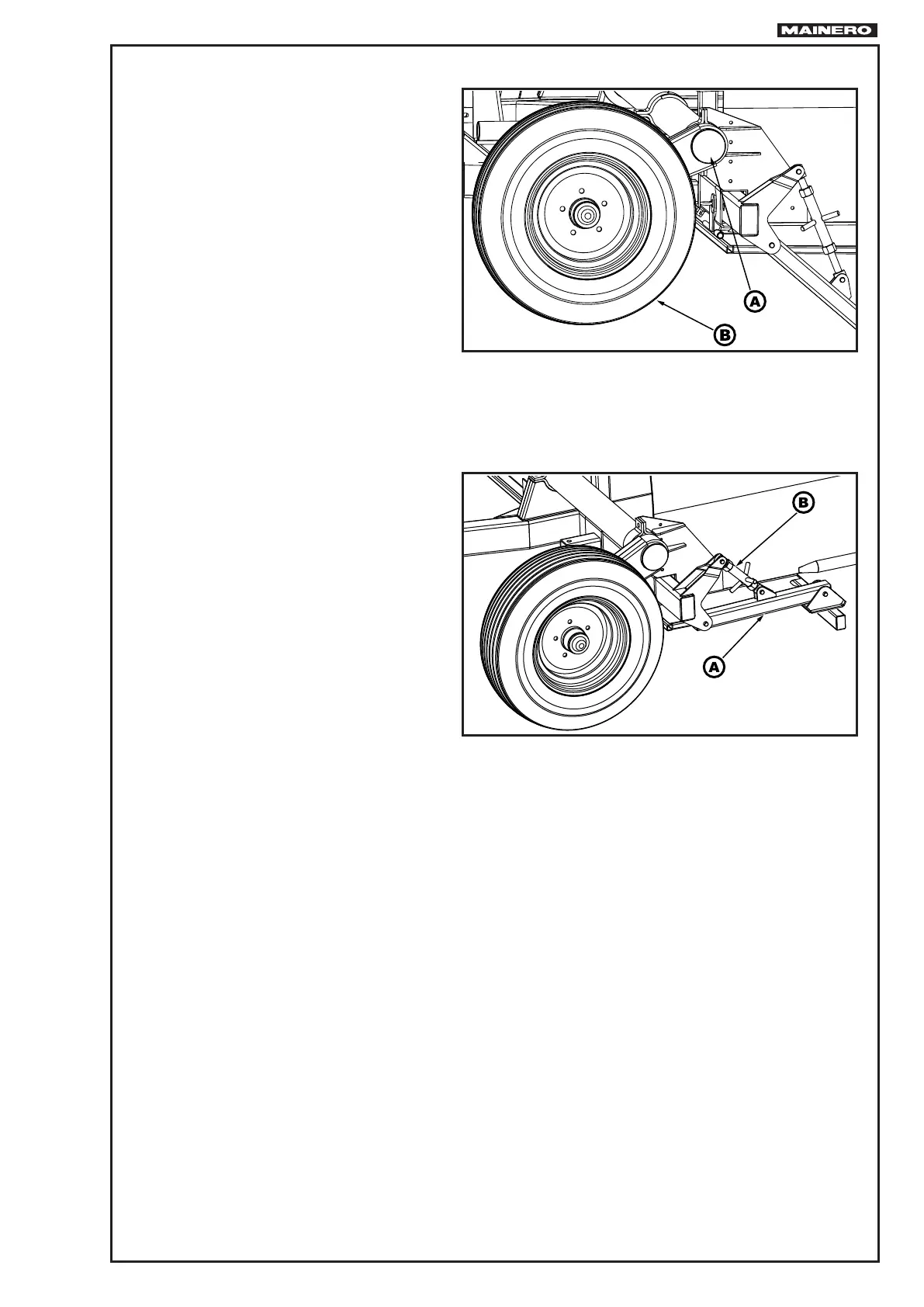
FIG.17
11. Close the hydraulic cylinder acting
from the tractor lever to raise the axle
“A” Fig. 16 and install the two wheels
“B”.
12. Open the hydraulic cylinder to raise
the machine and free the additional
support “A” Fig. 17. Close it from the
adjuster “B” and locate it underneath
the auger with the corresponding lock.
13.Install PTO shaft and verify that both
extreme couple in the slot of the striate
axle.
14. Execute from the tractor normal wor-
king movements, verify that the hoses
do not tight and do not interfere with
the PTO shaft.
15.Make rotate the TDP to low nº of
revolutions and then for some minutes
to working régime.