16
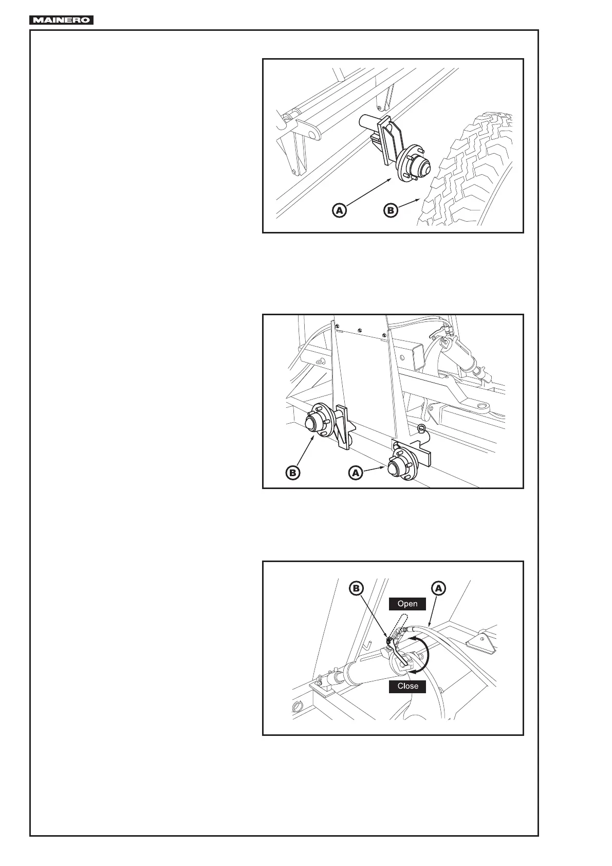
8. Withdraw the back wheel “B” Fig. 13
and the hub “A”, located into the lling
tunnel.
9. Put the back hub “A” Fig. 13 near to
the front hub “B” Fig. 14 with corres-
ponding bolts and locks.
10. Connect the hydraulico hoses “A” Fig.
15 to the tractor and open the valve “B”
located at the hydraulic cylinder.
FIG.13
FIG.14
FIG.15