19
PTO SHAFT
INSTALLATION
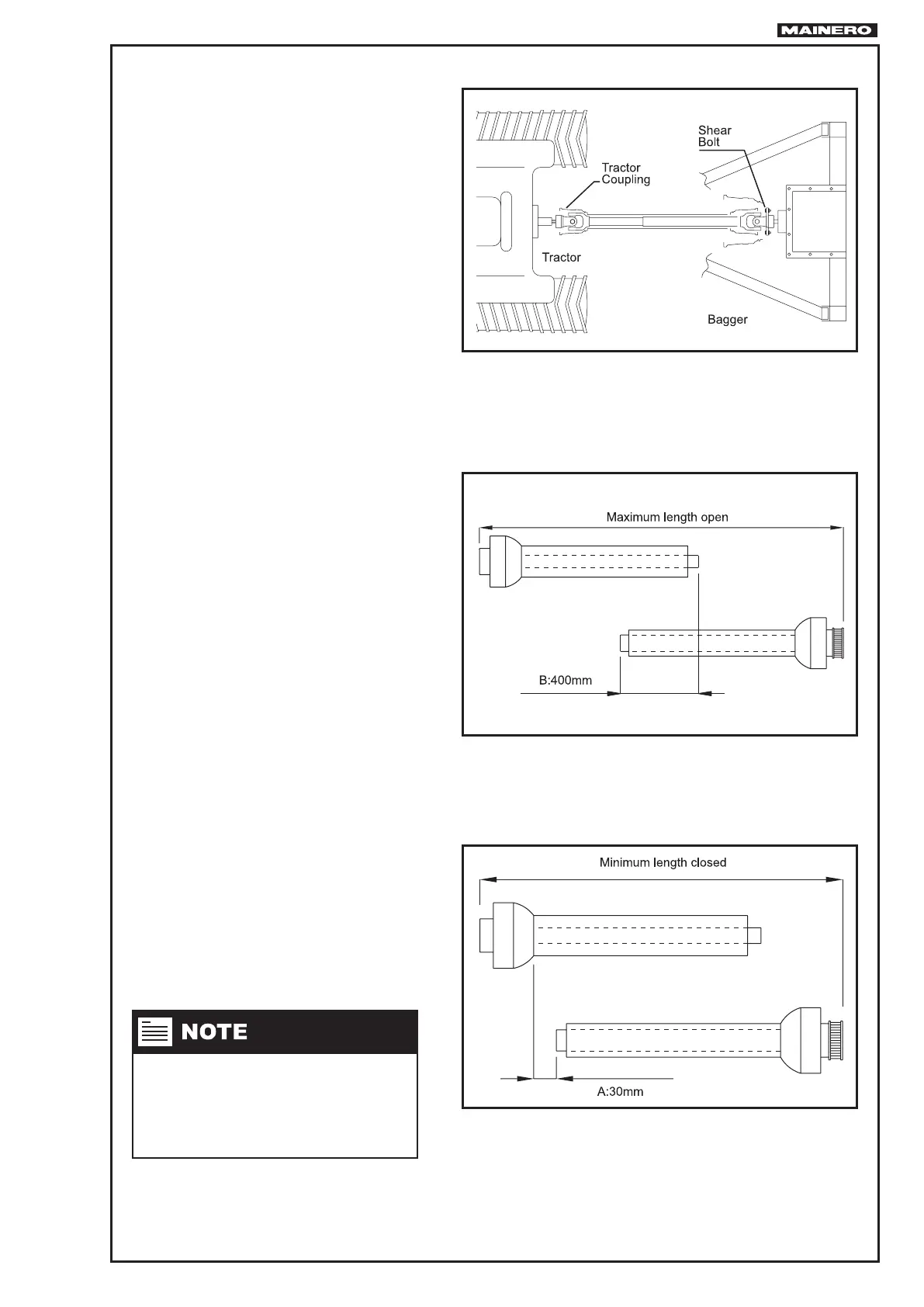
The PTO Shaft must be installed like is
shown in the Fig. 20, one end towards the
tractor and the end with shear bolt at the
imput shaft of the machine.
Prior to mounting we advice:
• Clean otu paint, oxide, etc, and lubri-
cate the splined ends of the axles were
the PTO shaft will t.
Verify length:
• Disassemble the PTO shaft in two par-
ts (uncouple male and female).
• With the machine in working position,
the male part coupled at the tractor
and the female part with shear bolt at
the machine, verify with the parts para-
llel to the PTO shaft have a “minimum
overlap of 400 mm” (between male
and female) Fig. 21.
• Verify when the shaft adopts the mini-
mum length, (closed turns, etc). The
telescopic sector must have a separa-
tion at least “30 mm” Fig. 22. In case of
being less cut in equal proportion the
extremes of both sliding metallic tubes,
as well as the plastic protections.
If the PTO shaft doesn´t t as a result
of the tractor draw bar is not standari-
zed, proceed to rectify one of them, to
obtain the values stated previously.
FIG.20
FIG.21
FIG.22