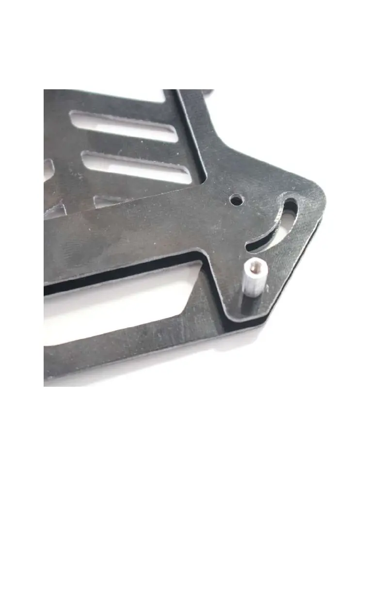
You can identify the boom holes in plates A and B pretty easily.
Both front and back mounting holes will have a single 3-mm
round hole positioned just above an arched 3-mm slot that
allows folding of the frame.
Figure 2-10. Rear boom mounting holes (notice the anchor hole
just above the folding slot).
Let’s continue by sandwiching the boom (plate C in Figure 2-3)
between the top and bottom dirty frame plates (plates A and B);
see Figure 2-11.
Airframes 27