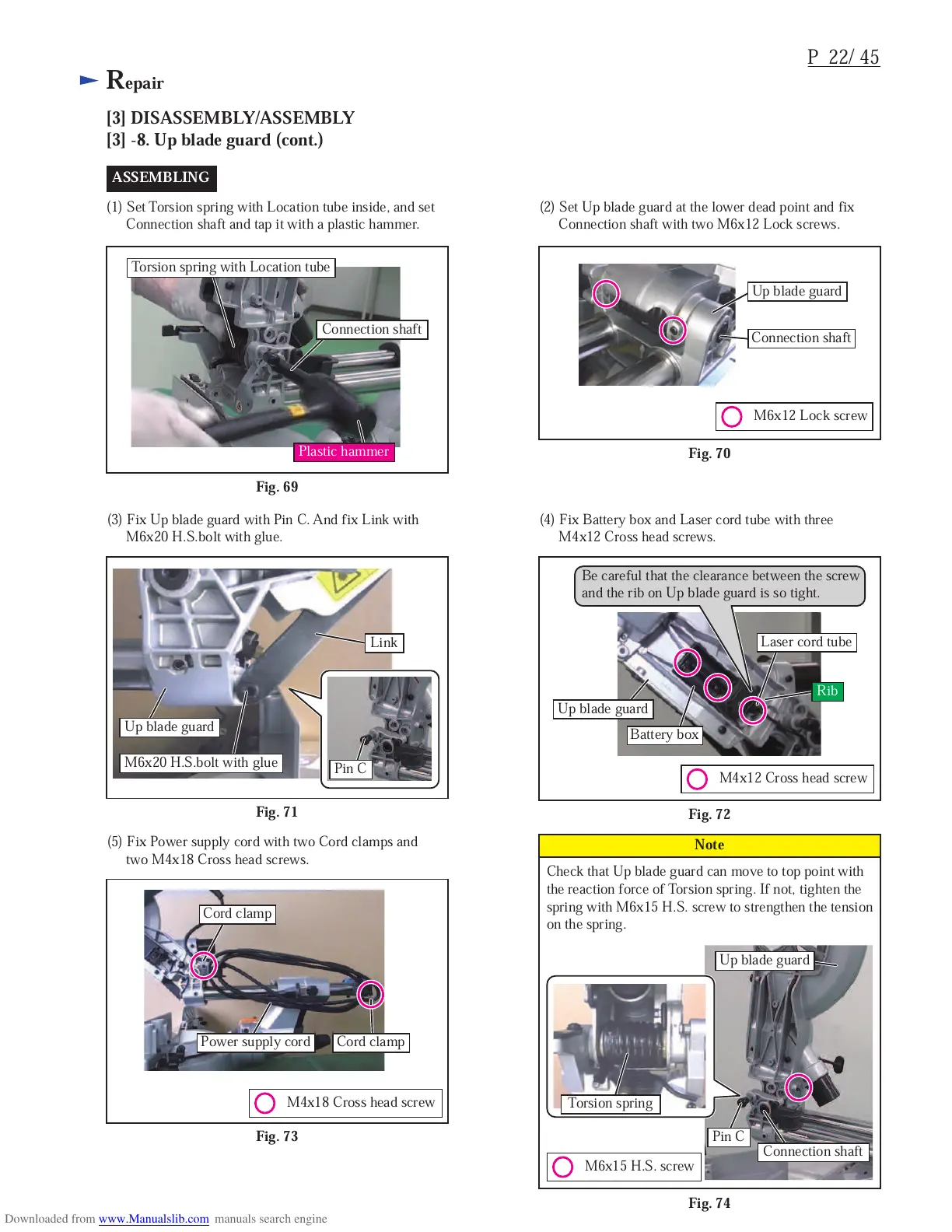
Pin C
Up blade guard
Connection shaft
M6x15 H.S. screw
Torsion spring
Fig. 74
Check that Up blade guard can move to top point with
the reaction force of Torsion spring. If not, tighten the
spring with M6x15 H.S. screw to strengthen the tension
on the spring.
Note
ASSEMBLING
Plastic hammer
Connection shaft
M6x12 Lock screw
Up blade guard
Connection shaft
(1) Set Torsion spring with Location tube inside, and set
Connection shaft and tap it with a plastic hammer.
(2) Set Up blade guard at the lower dead point and fix
Connection shaft with two M6x12 Lock screws.
Fig. 70
Fig. 69
Torsion spring with Location tube
(3) Fix Up blade guard with Pin C. And fix Link with
M6x20 H.S.bolt with glue.
Fig. 71
M6x20 H.S.bolt with glue
Link
Pin C
(5) Fix Power supply cord with two Cord clamps and
two M4x18 Cross head screws.
Fig. 73
Power supply cord
Cord clamp
Cord clamp
M4x18 Cross head screw
M4x12 Cross head screw
(4) Fix Battery box and Laser cord tube with three
M4x12 Cross head screws.
Battery box
Fig. 72
Laser cord tube
Be careful that the clearance between the screw
and the rib on Up blade guard is so tight.
Up blade guard
Up blade guard
Rib

 Loading...