P 26/ 45
Repair
[3] DISASSEMBLY/ASSEMBLY
[3] -9. Support arm (cont.)
Fig. 91
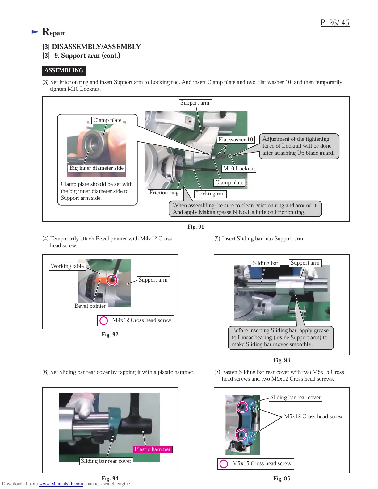
(3) Set Friction ring and insert Support arm to Locking rod. And insert Clamp plate and two Flat washer 10, and then temporarily
tighten M10 Locknut.
ASSEMBLING
Support arm
Flat washer 10
M10 Locknut
Clamp plate
Locking rod
Friction ring
Fig. 92
Fig. 93
(4) Temporarily attach Bevel pointer with M4x12 Cross
head screw.
(5) Insert Sliding bar into Support arm.
Fig. 94
Fig. 95
(6) Set Sliding bar rear cover by tapping it with a plastic hammer. (7) Fasten Sliding bar rear cover with two M5x15 Cross
head screws and two M5x12 Cross head screws.
Sliding bar rear cover
Plastic hammer
When assembling, be sure to clean Friction ring and around it.
And apply Makita grease N No.1 a little on Friction ring.
Adjustment of the tightening
force of Locknut will be done
after attaching Up blade guard.
Clamp plate should be set with
the big inner diameter side to
Support arm side.
M4x12 Cross head screw
Bevel pointer
Working table
Support arm
Sliding bar
Support arm
Before inserting Sliding bar, apply grease
to Linear bearing (inside Support arm) to
make Sliding bar moves smoothly.
M5x15 Cross head screw
M5x12 Cross head screw
Big inner diameter side
Clamp plate
Sliding bar rear cover

 Loading...