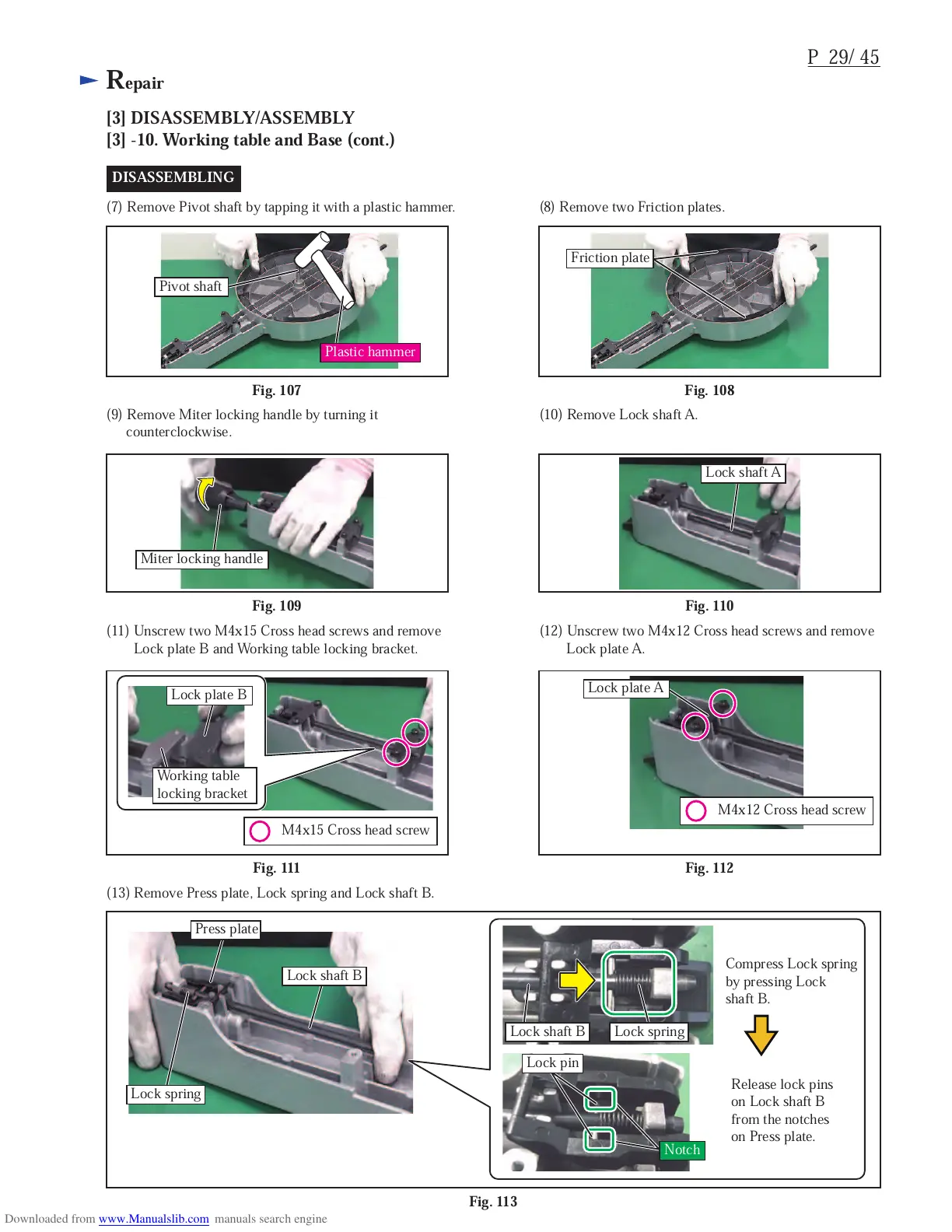
DISASSEMBLING
(7) Remove Pivot shaft by tapping it with a plastic hammer. (8) Remove two Friction plates.
Fig. 108
Fig. 107
(9) Remove Miter locking handle by turning it
counterclockwise.
(10) Remove Lock shaft A.
Fig. 110
Fig. 109
Fig. 112
Fig. 111
(11) Unscrew two M4x15 Cross head screws and remove
Lock plate B and Working table locking bracket.
(12) Unscrew two M4x12 Cross head screws and remove
Lock plate A.
Fig. 113
(13) Remove Press plate, Lock spring and Lock shaft B.
Press plate
Compress Lock spring
by pressing Lock
shaft B.
Release lock pins
on Lock shaft B
from the notches
on Press plate.
Lock shaft B
Lock spring
Notch
Lock pin
Lock spring
Lock shaft B
Friction plate
Pivot shaft
Miter locking handle
Lock shaft A
M4x12 Cross head screw
Lock plate A
M4x15 Cross head screw
Lock plate B
Working table
locking bracket
Plastic hammer
 Loading...