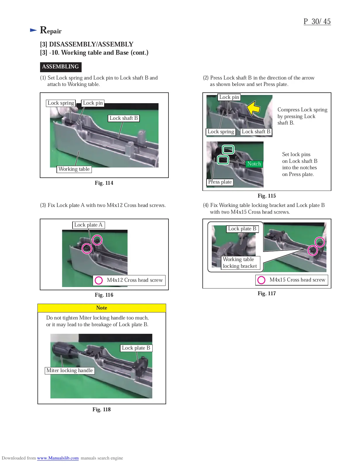
Fig. 114
Press plate
P 30/ 45
Repair
[3] DISASSEMBLY/ASSEMBLY
[3] -10. Working table and Base (cont.)
M4x15 Cross head screw
Lock plate B
Working table
locking bracket
ASSEMBLING
(1) Set Lock spring and Lock pin to Lock shaft B and
attach to Working table.
(2) Press Lock shaft B in the direction of the arrow
as shown below and set Press plate.
Fig. 115
Compress Lock spring
by pressing Lock
shaft B.
Set lock pins
on Lock shaft B
into the notches
on Press plate.
Lock shaft B
Working table
Lock shaft BLock spring
Lock spring Lock pin
(3) Fix Lock plate A with two M4x12 Cross head screws.
Fig. 116
M4x12 Cross head screw
Lock plate A
(4) Fix Working table locking bracket and Lock plate B
with two M4x15 Cross head screws.
Fig. 117
Fig. 118
Do not tighten Miter locking handle too much,
or it may lead to the breakage of Lock plate B.
Note
Lock plate B
Miter locking handle
Lock pin
Notch
 Loading...