National Crane Published 5-27-2018 Control # 039-06 10-1
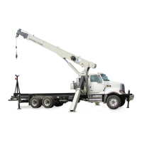
800D CRANE INSTALLATION
SECTION 10
CRANE INSTALLATION
SECTION CONTENTS
Pin Bearing Inspection And Installation
Procedure . . . . . . . . . . . . . . . . . . . . . . . . . . . . . . . 10-5
Pin Inspection . . . . . . . . . . . . . . . . . . . . . . . . . . . 10-5
Bearing Inspection . . . . . . . . . . . . . . . . . . . . . . . 10-5
Trunnion Inspection . . . . . . . . . . . . . . . . . . . . . . 10-5
Installation. . . . . . . . . . . . . . . . . . . . . . . . . . . . . . 10-5
Counterweighting . . . . . . . . . . . . . . . . . . . . . . . . 10-6
Counterweighting Methods For Stability
Around The Rear 180° . . . . . . . . . . . . . . . . . . . . . 10-9
Anti-two-block Rated Capacity Limiter
Installation And Function Verification . . . . . . . 10-11
Initial Crane Run in Procedure . . . . . . . . . . . . . 10-13
Boom Rests . . . . . . . . . . . . . . . . . . . . . . . . . . . . . 10-14
1. Determine installation position for the crane considering
the operating area of the crane, space for saddle tanks,
truck frame crossmembers, or anything that might affect
installation and be sure the frame is clear of any
obstructions that might interfere with proper installation.
2. Center the subbase on the chassis at the proper
location. Loosely assemble two mount anchor
assemblies per side to subbase and look for interference
with truck crossmembers.
3. If subbase does not fit tightly on truck frame at all
locations, do not force them together to remove gaps
since they will not affect the unit’s stiffness or strength.
Add spacers as required to level truck bed before
attaching it to the torsion box.
4. Drill four 3/4 in diameter holes through the truck frame at
each mounting plate using the holes in the mount
anchor assembly as pilot holes. Install 3/4 in diameter
Grade 8 bolts, washers and nuts in mounting plates.
5. With RSOD stabilizers retracted, determine the distance
from the top of the stabilizer frame cross tube to ground
level that will give you approximately 14 in (35 cm) of
ground clearance to the bottom of the stabilizer foot.
This will give approximately 11 in (27 mm) of stabilizer
penetration. Before final mounting the RSOD brackets
make sure that the tops of the stabilizer vertical cylinder
are below the top of the torsion box. Keep in mind that
the truck frame may settle slightly with the addition of the
crane frame, boom, bed and payload. Using this
determined vertical dimension, position the RSOD
mounting sub-assembly approximately 12 in (30 cm)
behind the rear tires. Check for truck frame bolt or rivet
interference. Cut clearance holes for rivet heads. Mark
and drill six 3/4 in bolt holes as specified through RSOD
mounting sub-assembly and truck frame and install six
3/4 in Grade 8 bolts, washers and nuts. Tighten to
proper torque.
Fo
r
Reference
Only

 Loading...


