OP32 – Installation manual
5. CONNECTING THE E83 RECEIVER
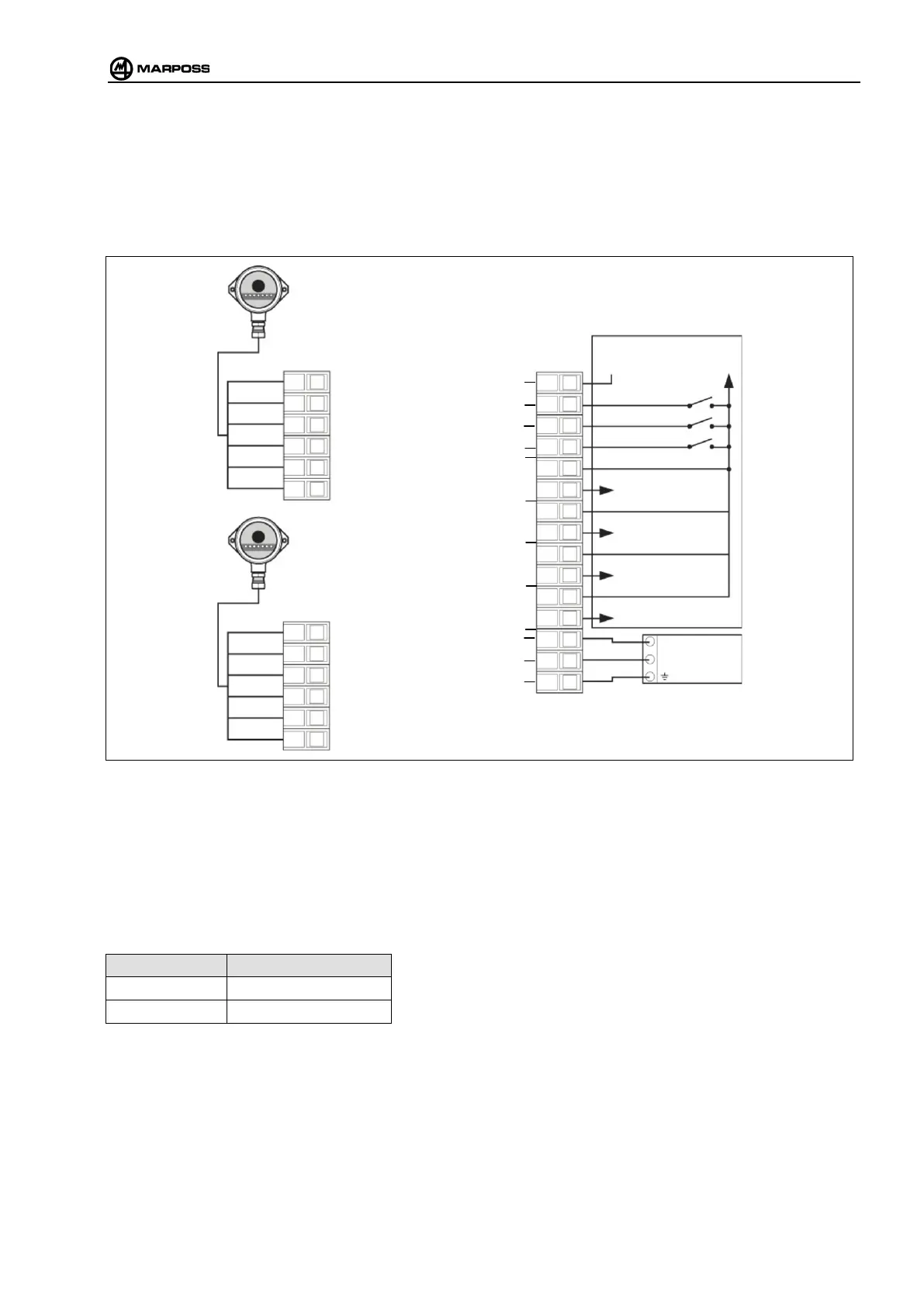
5.1 E83 interface unit connections
Connect the receiver to the interface unit as shown in the connection diagram below:
Figure 5-1. E83 interface unit connections.
5.1.1 Connecting the probe via cable with E32R
When using a cable application with the E32R interface, part no. 8303290070 (new or already installed on the machine),
the probe must be connected via cable (E32R SSR relay probe output) to E83 interface input 3 “AUX”.
Select either between the optical and cable systems according to the following table:
OPEN / 0V OPTICAL PROBE
24 V AUXILIARY PROBE
GREEN
RECEIVER 1
RECEIVER 2
(Optional)
1
AUX
START/STOP
BATTERY LOW
ERROR
CONDITION WITH SOURCE TYPE CONNECTION
SUPPLY