OP32 – Installation manual
7. TECHNICAL SPECIFICATION
7.1 OP32/OP32E Probe/Transmitter
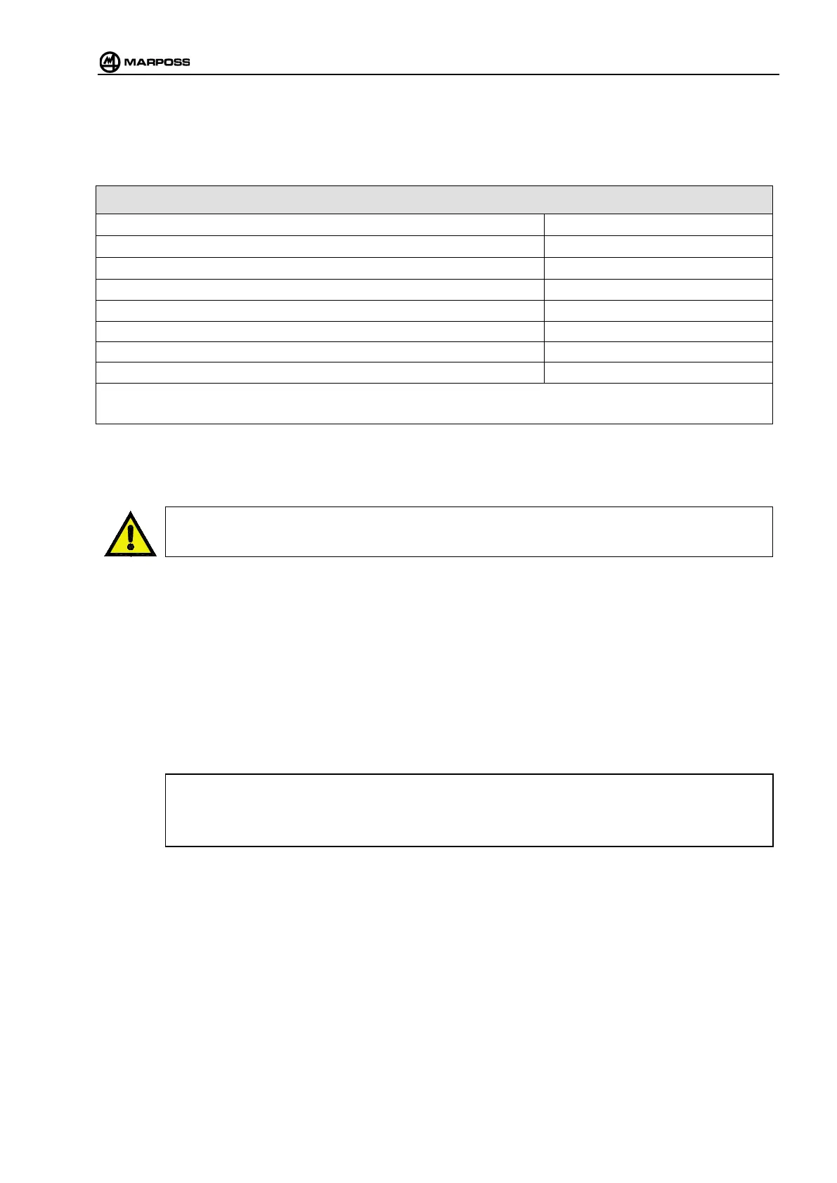
Table 7-1. Technical specifications for measuring probe.
Probe axes
±X, ±Y, + Z
Probe single direction repeatability (2σ) at a velocity of up to 600 mm/min.
1 μm
X, Y plane measuring force
0.5÷0.95 N ± 20%
Z direction measuring force
5.8 N ± 20%
8 mm
3,5 mm
Operating temperature:
from 0°C to 60°C
IEC protection rating
IP68
N.B.: data measured using a 35mm finger.
7.2 E83 Interface unit
ATTENTION
The receiver cable should be located away from conductors carrying high voltages and currents, especially
if these are connected to switched-mode power supplies.
24 VDC unstabilised (18 – 35 V) SELV type (safety extra low voltage) according with EN60950-
1300mA rule
300mA max with two receivers connected.
Input signals
optoisolated inputs 24 V – 10 mA
AUX:
Select probe. This signal is required only when multiple transmitters are installed.
start/stop transmission.
Signal leading edge = start.
Signal lagging edge = stop (only if interface unit dip-switch H2 is in position OFF).
See “Programming the interface unit”.
The signal may be connected as SINK or SOURCE:
• SINK connect “COM” to the “+24V”.
•
SOURCE connect “COM” to “0 V”.
Output signal : 48V – 40mA solid state relay (SSR) contacts, with electronic protection against overloads and short
circuits.
When the protection device intervenes, the red error LEDs begin to flash, while all the other LEDs switch off.
To reset the protection device send a start signal and disconnect the power supply momentarily (red wire).
ERROR : (normally closed contact - N.C.). Communication error (probe disabled, obstacle present in optical path, probe
outside transmission range, optical interference, transmitter battery completely discharged). Output signal indicated by
switching on the front panel “error” LED. When the cause of the error has been removed, the system will start working
correctly again (automatic error reset).
PROBE 1 : (normally open/normally closed contact - N.O./N.C., programmable via the dip-switch H 6 - “Programming the
interface unit”).
Output signal indicating the state of the probe in use (probe at rest or probe deflected).