mida
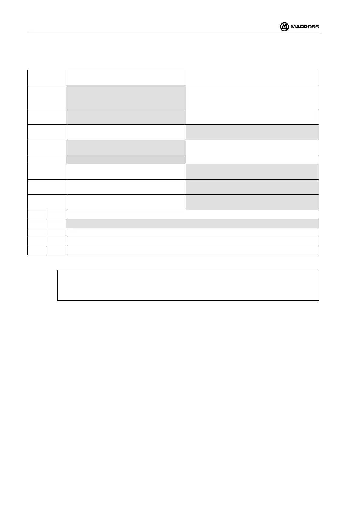
Use the dip-switch (H) to program the operating mode, in accordance with the table (the factory-set configuration is
indicated inside the grey border):
DIP-SWITCH
(H)
OFF ON
1
Signal reception: normal
En
sure maximum immunity from optical
interference by other light sources.
Signal reception: fast.
2
Transmission stopped by logic signal (input
signal lagging edge START).
Transmission stopped automatically after fixed period
(3’ 21”).
3
Automatic transmission start. The interface unit emits
a continuous signal until it receives a valid signal.
Transmission started by a logic signal or the START
signal (START input signal leading edge).
4
PROBE 2 output = SKIP (pulse each time probe
changes state).
PROBE 2
output = PROBE (probe state; at rest or
deflected).
5
Debouncing = 200 ms. Debouncing = 20 ms.
6
PROBE 1 output contact = N. C. (normally
closed).
PROBE 1 output contact = N. O. (normally open).
7
PROBE 2 output contact = N. C. (normally
closed).
PROBE 2 output contact = N. O. (normally open).
8
LOW BAT output contact = N. C. (normally
closed).
LOW BAT output contact = N. O. (normally open).
9 10
OFF OFF Normal operation
ON OFF Channel 2 self test
OFF ON Channel 1 self test
ON ON reserved
E83 –
DIP SWITCH 3 = automatic transmission start. The interface unit continues to emit start signals until
it receives a valid signal.
The grey borders indicate the default dip-switch positions.